Back to dashboard
Sections menu

Boeing 737-800 NG · Components

Components by ATA chapter

Every ATA chapter has its own components page. Pick a chapter, then a part: what it is made of, how it works, what it connects to, the numbers that matter, how it fails and how mechanics inspect it.

Unverified — check your manualText on this page is written from general knowledge. Figures marked ✓ are checked against official FAA/EASA data.See verified data

ATA 21 · Air Conditioning & Pressurisation

ATA 21 Air Conditioning & Pressurization

Air conditioning pack

Cools hot bleed air with an air cycle machine.

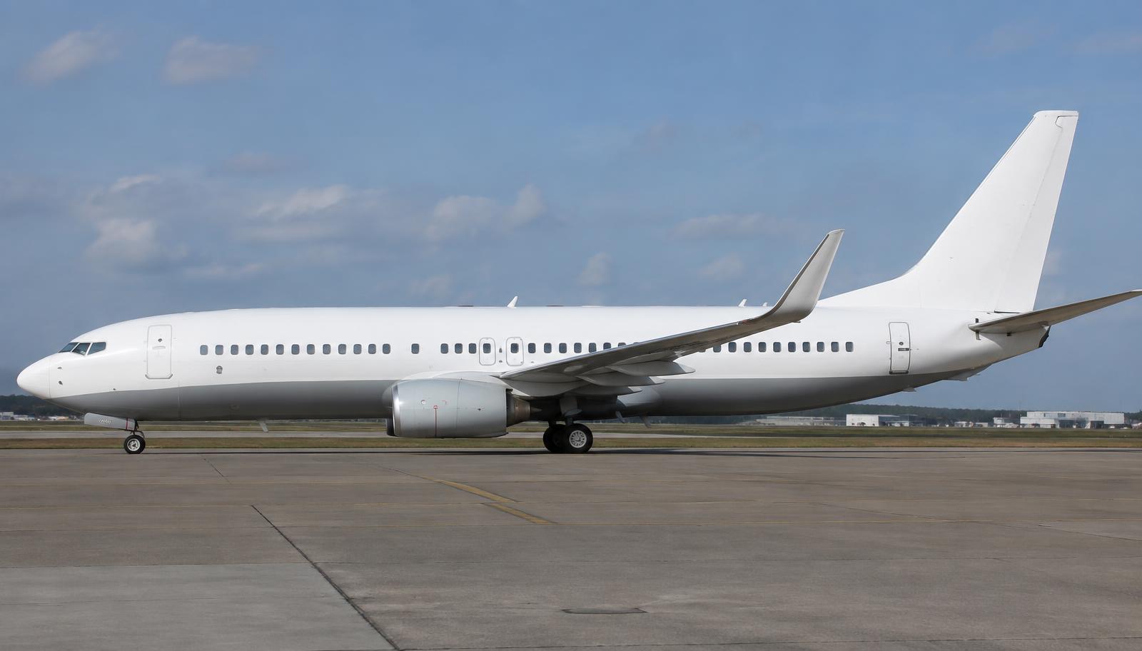
Location: Under the wing-to-body fairing.
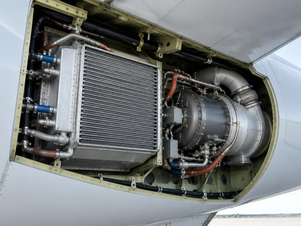
Air conditioning pack on the Boeing 737-800 NG
Air conditioning pack · illustrative image

Where it is

Location of Air conditioning pack
Air conditioning pack

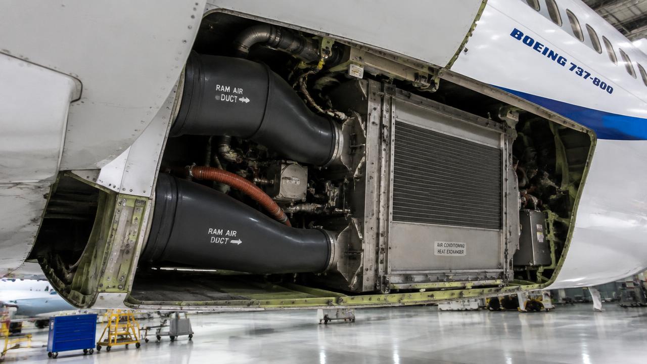
What it looks like

Pack bay with ram air ducts and heat exchanger
Pack bay with ram air ducts and heat exchanger · illustrative image

How it works

Bleed air passes through primary heat exchanger, compressor, secondary heat exchanger, turbine — expansion cools it well below freezing.

A water separator removes moisture; mix valves set temperature.

The ACM cools air by compressing and then expanding it through a turbine; a water separator removes moisture.

Temperature controllers mix hot trim air to reach the selected zone temperature.

Construction

  • Air-cycle machine (bootstrap): primary/secondary heat exchanger, compressor, turbine, water separator, ram air inlet/exit doors.
  • Pack valve controls flow; temperature controller modulates mix valves.

Interfaces with other systems

  • Bleed duct, pack controller, ram-air doors, mix manifold, recirculation fans, zone temperature control.

Technical data

Packs2
ModeAUTO / HIGH
Number2
Ram airDoors open more on the ground

Failure modes

Pack tripOverheat — PACK light.
ACM seizureNo cooling.
Pack trip offOverheat — reset when cooled.

Inspection

  • Heat exchanger cleaning.
  • Water separator bag.
  • Clean heat exchangers.
  • Check ram-air door actuator.

Note

PACK light: overheat trip; reset with TRIP RESET after cooling.

Ram doors open on ground for cooling; deflector door protects inlet on ground.

Educational summary — verify against the component maintenance manual (CMM) and AMM.

All parts in ATA 21

1.Packs (2)

Air-cycle machines.

Two air-cycle machine (ACM) packs mounted in the wing-to-body fairing below the center fuselage, one left and one right, each fed by bleed air from its respective engine, the APU, or the opposite side via the isolation valve.

How it works
  • Hot bleed air is cooled by ram-air heat exchangers, then expanded across a turbine that drives a compressor and fan, producing cold, moisture-laden air.
  • A water extractor removes condensation before the air enters the mix manifold.
  • Pack flow and temperature are modulated by the pack temperature control valve and ram air modulating doors, both commanded by the Equipment Cooling/Pressurization logic or, on later 737s, the ADIRU-fed environmental control system.
  • Each pack can be selected AUTO, HIGH, or OFF from the cockpit AIR COND panel.
Pack flow (AUTO)approx. 0.4-0.8 lb/min per passenger equivalent
Bleed air supply pressureapprox. 30-45 psi regulated
Turbine inlet temperature limitapprox. 450 F max
Pack discharge temperature range0 C to 90 C
Failures
  • Pack overheat/trip: PACK light illuminates, pack automatically shuts off, crew selects remaining pack or APU bleed
  • Pack valve fails closed: Loss of conditioned air flow from that side, duct pressure drops
  • Water extractor clogging: Reduced cooling performance, possible moisture ingestion into cabin
Inspection
  • Inspect pack bay for bleed air leaks and heat damage during line checks.
  • Functional test of pack temperature control valve and ram air doors.
  • Check water extractor and sock filter for contamination at scheduled intervals.

2.Recirculation fans

Two electrically driven centrifugal fans located in the forward cargo compartment ceiling area, each supplying one side of the mix manifold by drawing cabin return air through HEPA-equivalent filters.

How it works
  • Each fan is a 115V 3-phase AC motor-driven impeller controlled by its own relay/contactor from the P6 panel.
  • Return air from the cabin is mixed with pack discharge air in the mix manifold to balance temperature and reduce total bleed demand.
  • A smoke detection or pack failure will automatically trip the associated recirc fan off to prevent smoke recirculation.
Fan motor powerapprox. 0.75 hp, 115 VAC
Flow contributionapprox. 50% of total mix manifold airflow
Filter typehigh-efficiency particulate filter elements
Failures
  • Fan failure: RECIRC FAN light on, reduced total airflow, slightly warmer cabin temperature
  • Filter clogging: Reduced flow, increased fan motor load, possible overheat trip
Inspection
  • Inspect/replace recirculation filters per maintenance interval.
  • Check fan bearing noise and current draw during ground run checks.

3.Mix manifold

A sheet-metal plenum located above the forward cargo compartment where conditioned air from both packs and recirculated cabin air combine before distribution to the cabin risers and flight deck.

How it works
  • Pack discharge air and recirculation fan output merge in the manifold, equalizing pressure and temperature before being ducted upward through riser ducts to overhead distribution nozzles.
  • Manifold pressure balance ensures even flow split between zones even if one pack is inoperative.
Manifold locationstation area forward cargo compartment ceiling
Distribution zonesflight deck, forward cabin, aft cabin
Failures
  • Duct leak/rupture in manifold: Uneven cabin temperature, possible duct overheat warning
  • Blocked riser duct: Localized zone loses airflow
Inspection
  • Visual inspection of manifold ducting and clamps for cracks or leaks.
  • Check duct overheat loop wiring routed near the manifold.

4.Outflow valve

A single butterfly-type outflow valve mounted in the lower aft fuselage, just forward of the aft cargo compartment, that regulates cabin pressure by metering air overboard.

How it works
  • Commanded by the digital cabin pressure controller (CPC), which schedules cabin altitude based on flight altitude and a programmed landing field elevation.
  • The valve is driven by a dual electric actuator (primary and standby controllers) with a manual backup rotary control in the cockpit.
  • Valve position modulates continuously to maintain the scheduled cabin rate of climb/descent, typically limited to 500 fpm or less.
Max differential pressureapprox. 8.35-8.65 psi
Normal cabin rate of changeup to 500 fpm, higher on emergency depress
Actuator typedual redundant electric motor driven
Failures
  • Valve fails full open: Cabin cannot pressurize, altitude horn/warning, emergency descent may be required
  • Valve fails closed/stuck: Cabin overpressure risk, pressure relief valves activate
Inspection
  • Functional check of CPC auto/standby modes and valve travel.
  • Inspect valve seals and linkage for wear or corrosion.

5.Pressure relief valves

Spring-loaded negative and positive pressure relief valves mounted in the aft fuselage near the outflow valve, protecting the fuselage pressure vessel from over- or under-pressurization.

How it works
  • The positive relief valve opens if cabin differential pressure exceeds a set limit above normal operating differential, venting air overboard independent of the CPC.
  • A negative pressure relief valve (often combined with the forward or aft valve) allows outside air in if cabin pressure drops below ambient, preventing structural implosion on the ground after a hot/cold soak.
Positive relief settingapprox. 8.65-8.9 psi differential
Negative relief settingapprox. -0.5 to -1.0 psi differential
Failures
  • Relief valve leaks/sticks open: Cabin cannot build normal differential pressure
  • Relief valve fails to open: Structural overpressure risk in a pressurization control malfunction
Inspection
  • Ground functional test of relief valve cracking pressure.
  • Inspect valve seat and gasket for leakage during pressurization checks.

EDUCATIONAL USE ONLY. Content is summarised from manufacturer documentation for learning. It is not approved flight or maintenance data. Always use the current, aircraft-specific POH/AFM, FCOM, QRH, AMM and operator procedures.