Back to dashboard
Sections menu

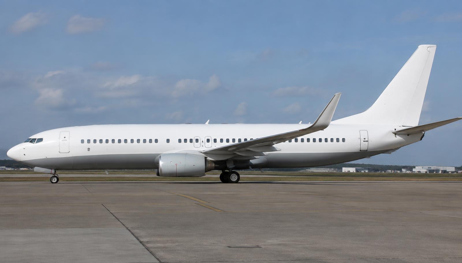
Boeing 737-800 NG · Interactive FCOM

Full manual

Organised like the official Flight Crew Operating Manual with maintenance by ATA chapter. Search across every section.

Unverified — check your manualText on this page is written from general knowledge. Figures marked ✓ are checked against official FAA/EASA data.See verified data
1

General

EnginesCFM56-7B (NG) / LEAP-1B (MAX)
MTOW79,016 kg (-800)
Typical seats162–189
Range~2,935 nm
MMOM 0.82
Ceiling41,000 ft

Model applicability

  • 737-800 NG — 1998 – 2020 · S/N By line number / tab — see FCOM preface
  • 737 MAX 8 — 2017 – present · S/N By line number
2

Limitations

Speeds

VMO / MMO✓ FAA340 kt / M 0.82
Gear extended / extension320 kt / M 0.82 · 270 kt / M 0.82
Gear retraction235 kt
Max demonstrated crosswind (guidance)33 kt

Flight envelope

Max operating altitude✓ FAA41,000 ft
Load factor flaps up+2.5 / −1 g
Load factor flaps down+2 / 0 g

Engine (CFM56-7B)

EGT takeoff limit950 °C
EGT start limit725 °C
Starter cutout56% N2
3

Abnormal & Emergency Procedures

Engine Fire / Severe Damage / Separation

Autothrottle (if engaged)DISENGAGE
Thrust lever (affected)CLOSE
Engine start lever (affected)CUTOFF
Engine fire switch (affected)PULL
Engine fire switchROTATE to stop & hold 1 s
If after 30 s still illuminatedROTATE to other stop & hold 1 s

QRH memory items. Source: 737 QRH Section 8.

Rejected Takeoff

Thrust leversCLOSE
AutothrottleDISENGAGE
BrakesMAXIMUM MANUAL (or verify RTO autobrake)
Speed brakesUP
Reverse thrustMAX consistent with conditions
ATCNOTIFY

Runaway Stabilizer

Control columnHOLD FIRMLY
Autopilot (if engaged)DISENGAGE
Autothrottle (if engaged)DISENGAGE
If runaway continues: STAB TRIM CUTOUT switchesCUTOUT (both)
If runaway continues: Stabilizer trim wheelGRASP & HOLD

Cabin Altitude Warning / Rapid Depressurization

Oxygen masks & regulatorsON, 100%
Crew communicationsESTABLISH
Pressurization mode selectorMAN
Outflow valve switchCLOSE
If cabin alt uncontrollable: Pax oxygen switchON
Emergency descentINITIATE
4

Normal Procedures

Expanded, step-by-step versions with explanations: open the interactive procedures →

APU Start (amplified)

  1. 1. Battery switch — ON (guard closed)
    Powers APU start circuitry.
  2. 2. Left aft fuel pump (if AC available) — ON
    Provides positive fuel pressure to the APU, reducing wear on its fuel control.
  3. 3. APU switch — START (hold, release to ON)
    Spring-loaded START position initiates the sequence.
  4. 4. APU GEN OFF BUS light — ILLUMINATED (blue)
    APU is running and ready to power the busses.
  5. 5. APU GEN switches — ON BUS
    Transfers both busses to APU power.
  6. 6. APU BLEED — ON
    Supplies air for packs and engine start.

Engine Start (amplified)

  1. 1. ANTI-COLLISION light — ON
    Mandatory before start.
  2. 2. PACK switches — OFF
    Maximises duct pressure available for the starter.
  3. 3. Duct pressure — CHECK (~30 psi min, adjusted for altitude)
    Insufficient pressure → slow/hung start.
  4. 4. ENGINE START switch 2 — GRD
    Opens start valve; air turbine starter spins N2.
  5. 5. N2 rotation & oil pressure — VERIFY
    Oil pressure must rise; N1 rotation by 40% N2.
  6. 6. Engine start lever 2 — IDLE at 25% N2 (or max motoring, min 20%)
    Introduces fuel and ignition at the right rotor speed.
  7. 7. Fuel flow, EGT — MONITOR
    EGT rises as light-off occurs; watch for hot start.
  8. 8. ENGINE START switch — Moves to OFF at 56% N2
    Starter cutout — if it doesn't, move it OFF manually.
  9. 9. Engine stabilised at idle — CHECK
    Then repeat for engine 1.

Shutdown (amplified)

  1. 1. Parking brake — SET
    Before cutting the engines.
  2. 2. Electrical power — APU / EXT PWR ON BUS
    Ensures uninterrupted power.
  3. 3. Engine start levers — CUTOFF
    Shuts off fuel and ignition.
  4. 4. ANTI-COLLISION light — OFF
    Engines spooled down.
  5. 5. FUEL PUMPS — OFF
    No longer needed.
  6. 6. HYD pumps — OFF / as required
    Electric pumps off unless ground crew need pressure.

Takeoff (amplified)

  1. 1. Thrust levers — ADVANCE to approx. 40% N1, stabilise
    Symmetrical spool-up.
  2. 2. TO/GA switch — PRESS
    Autothrottle sets takeoff N1.
  3. 3. FMA — N1 / TO/GA — VERIFY
    Correct modes.
  4. 4. Engine instruments — MONITOR
    Callouts if exceedance.
  5. 5. Callouts — 80 kt (THR HLD), V1, ROTATE
    Crew cross-check.
  6. 6. Rotate — Approx. 2–3°/s to 15°
    Avoid tail strike.
  7. 7. Positive rate — GEAR UP
    Drag.
  8. 8. Autopilot — ENGAGE above 400 ft
    Workload.
  9. 9. Flaps — RETRACT on schedule
    Speed bugs.

ILS Approach & Landing (amplified)

  1. 1. APP mode — ARM — VOR/LOC and G/S
    Captures the ILS.
  2. 2. Flaps — 1 → 5 → 15 → GEAR DOWN → 30
    Configure at manoeuvre speeds.
  3. 3. Speed brake — ARMED
    Automatic ground spoilers.
  4. 4. Autobrake — SET (1/2/3/MAX)
    Deceleration rate.
  5. 5. Stabilised — BY 1,000 ft
    Go-around otherwise.
  6. 6. Autopilot — DISENGAGE by minimums (manual landing)
    Hand fly the flare.
  7. 7. Flare and idle — THRUST LEVERS CLOSE
    Touchdown.
  8. 8. Reverse thrust — AS REQUIRED, idle by 60 kt
    Avoid FOD ingestion and compressor stalls.

Rejected Takeoff (amplified)

  1. 1. Thrust levers — CLOSE
    Disconnects autothrottle.
  2. 2. Autothrottle — DISENGAGE
    Prevents re-advance.
  3. 3. Braking — VERIFY RTO autobrake / MAX manual
    Max deceleration.
  4. 4. Speed brakes — VERIFY UP
    Weight onto wheels.
  5. 5. Reverse thrust — MAX as needed
    Additional stopping force.
  6. 6. Notify — ATC and cabin
    Fire services.
  7. 7. Parking brake / evacuation — AS REQUIRED
    Hot brakes — consider evacuation checklist.

Engine Failure after V1 (amplified)

  1. 1. Rotate — VR, approx. 12–13°
    V2 to V2+20.
  2. 2. Rudder — STEP ON THE GOOD ENGINE
    Control yaw; centre control wheel.
  3. 3. Positive rate — GEAR UP
    Drag.
  4. 4. Engine-out altitude — LEVEL / accelerate
    Clean up.
  5. 5. Thrust — MCT
    Single-engine climb.
  6. 6. Non-normal checklist — COMPLETE
    Identify and secure engine.

Preliminary Cockpit Preparation (amplified)

  1. 1. Battery — ON, guard closed
    Powers the hot battery bus.
  2. 2. Standby power — AUTO
    Automatic transfer to battery.
  3. 3. APU — START
    Electrical and bleed power.
  4. 4. IRS mode selectors — NAV
    Alignment approx. 10 min.
  5. 5. FMC — POS INIT, ROUTE, PERF INIT
    Flight plan entry.
  6. 6. MCP — SET course, speed, heading, altitude
    Clearance.
  7. 7. Hydraulic pumps — ELEC ON (check ground crew clear)
    Pressurise for control checks.

FMC Preflight & Route Entry (amplified)

  1. 1. IDENT page — CHECK model, engine & nav data
    Current database.
  2. 2. POS INIT — ENTER gate / GPS position into SET IRS POS
    Aligns IRS.
  3. 3. RTE page 1 — ORIGIN, DEST, RUNWAY, FLT NO
    Route basics.
  4. 4. RTE page 2 — VIA (airway) / TO (fix) entries
    Builds the route.
  5. 5. DEP/ARR — SELECT SID and runway; STAR later
    Departure procedure.
  6. 6. ACTIVATE → EXEC — PRESS
    The route becomes active only after EXEC.
  7. 7. LEGS page — CHECK vs flight plan; clear discontinuities
    Both pilots cross-check.
  8. 8. PERF INIT — ZFW, fuel, reserves, CI, CRZ ALT
    Weight and performance.
  9. 9. TAKEOFF REF — Flaps, V1/VR/V2, derate / assumed temp
    Takeoff speeds set on the speed tape.

Autopilot & Autothrottle (MCP) (amplified)

  1. 1. Flight directors — ON (PF side first)
    Guidance for takeoff.
  2. 2. A/T ARM — ARM
    Autothrottle ready for N1 on takeoff.
  3. 3. LNAV / VNAV — ARM / SELECT after takeoff (LNAV above 50 ft, VNAV above 400 ft typical)
    Follow FMC route and profile.
  4. 4. CMD A — PUSH (above 400 ft)
    Engages autopilot A; check CMD on FMA.
  5. 5. ALTITUDE window — SET cleared level
    Autopilot won't climb or descend through it.
  6. 6. LVL CHG / V/S — Use for tactical changes
    LVL CHG: speed on elevator, thrust fixed; V/S: set rate.
  7. 7. HDG SEL — For ATC vectors
    Leaves LNAV.
  8. 8. VOR LOC / APP — ARM for ILS; CMD B for dual autoland
    Captures localiser and glideslope.
  9. 9. AP disconnect — Switch on control wheel
    Press twice to silence the warning.

Go-Around & Missed Approach (amplified)

  1. 1. TO/GA switch — PUSH
    A/T advances to GA thrust, FD commands go-around pitch.
  2. 2. Rotate — Approx. 15° nose up
    Follow the flight director.
  3. 3. Flaps — 15
    Go-around flap setting.
  4. 4. Positive rate — Gear UP
    Reduces drag.
  5. 5. Above 400 ft — Select roll mode (LNAV/HDG)
    Follow the missed approach.
  6. 6. At acceleration height — Select LVL CHG / retract flaps on schedule
    Clean up while climbing.

Engine Fire / Severe Damage (amplified)

  1. 1. Autothrottle — DISENGAGE
    Memory item.
  2. 2. Thrust lever (affected) — CLOSE — confirm
    Both pilots confirm the engine.
  3. 3. Start lever (affected) — CUTOFF — confirm
    Shuts fuel at the engine.
  4. 4. Engine fire switch — PULL — confirm
    Closes fuel, hydraulics, bleed, generator trips.
  5. 5. Engine fire switch — ROTATE to stop, hold 1 s
    Discharges a bottle.
  6. 6. If after 30 s still on — ROTATE to other stop
    Second bottle.

Cruise Monitoring (amplified)

  1. 1. PROGRESS page — CHECK fuel at destination
    Compare with plan each waypoint.
  2. 2. Fuel quantity — CHECK balance
    Imbalance > 1,000 lb (typical) needs crossfeed.
  3. 3. Center tank pumps — OFF when center tank empty
    Prevents pumps running dry.
  4. 4. Step climb — Evaluate on VNAV CRZ page
    Saves fuel as weight drops.
  5. 5. Weather radar — SET tilt / range
    Avoid thunderstorms.

After Landing & Parking (amplified)

  1. 1. Speedbrake — DOWN
    Clear of the runway.
  2. 2. Flaps — UP
    Prevent damage from debris.
  3. 3. APU — START (as required)
    Power before engine shutdown.
  4. 4. Parking brake — SET
    Hold at the gate.
  5. 5. Start levers — CUTOFF
    Engines shut down.
  6. 6. Anti-collision light — OFF
    Ground crew may approach.
  7. 7. Fuel pumps — OFF
    Not needed.

Exterior Inspection — Nose Area

Probes, sensors, portsCLEAR, NO DAMAGE
Nose gear steering lockout pinINSTALL / AS REQUIRED
Nose tires, strut, doorsCHECK
Radome & windowsCONDITION

Wings & Engines

Engine inlet, fan, cowlCONDITION
Exhaust & reverserSTOWED
Leading edges / Kruegers / slatsCONDITION
Wingtip, winglet, lightsCONDITION
Trailing edge flaps & spoilersCONDITION
Main gear, brakes, wheel wellsCHECK
Fuel measuring sticksFLUSH & SECURE

Tail Area

Stabilizer, elevator, rudderCONDITION
APU inlet / exhaustCLEAR
Tail skidCONDITION
Outflow valveCHECK

Flight Deck Preflight

Battery switchON, guard closed
IRS mode selectorsNAV
Fuel & hydraulic panelsCHECK
OxygenTEST
FMC (POS, ROUTE, PERF)COMPLETE
MCPSET

Before Start

Flight deck doorCLOSED & LOCKED
Fuel___ KGS, PUMPS ON
Passenger signsSET
WindowsLOCKED
MCPV2 ___, HDG ___, ALT ___
Takeoff speedsV1, VR, V2
CDU preflightCOMPLETED
Rudder & aileron trimFREE & 0
Taxi & takeoff briefingCOMPLETED
Anti-collision lightON

Takeoff

Thrust leversADVANCE to ~40% N1, stabilize
TO/GAPUSH
80 ktCHECK
V1CALL
VRROTATE
Positive rateGEAR UP
FlapsRETRACT on schedule

Landing

Engine start switchesCONT
Speed brakeARMED
Landing gearDOWN
Flaps___, GREEN LIGHT
5

Performance

Airline performance is computed with the operator's approved performance software (e.g. Airbus FlySmart / Boeing OPT) — not tabulated here.

7

Airplane & Systems Description

Flight Deck ATA 22, 23, 31, 34, 35

Where it is

Location of Flight Deck
Flight Deck

Six-screen Common Display System with conventional control columns and the dual-FMC flight management system.

  • Control columns and wheels move cables to hydraulic power control units (PCUs) — no fly-by-wire on the NG; manual reversion if hydraulics are lost.
  • Autopilot Flight Director System (AFDS) with two FCCs; Mode Control Panel (MCP) on the glareshield.
  • Two Air Data Inertial Reference Units (ADIRUs) provide attitude and air data.
  • Master Caution with system annunciator 'six-pack' panels; failures are handled with the paper/electronic QRH.

CFM56-7B Turbofans ATA 26, 36, 71, 72, 73, 74, 78, 79

Where it is

Location of CFM56-7B Turbofans
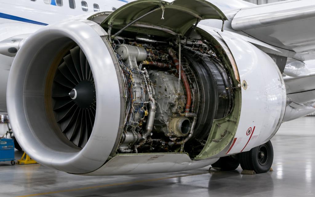
CFM56-7B Turbofans

What it looks like

CFM56-7 with fan cowl open — note the flattened lower nacelle
CFM56-7 with fan cowl open — note the flattened lower nacelle · illustrative image

Two high-bypass turbofans with EEC (Electronic Engine Control) and the distinctive flat-bottomed nacelles.

  • The EEC sets N1 based on thrust lever position; normal and alternate modes.
  • Engine-driven hydraulic pumps: ENG 1 → System A, ENG 2 → System B (plus electric pumps on the opposite system).
  • Integrated Drive Generators provide 90 kVA AC per engine.
  • Flattened 'hamster pouch' nacelle bottom gives ground clearance for the large fan on the low-slung 737.
  • Fire detection by dual loops; two shared extinguisher bottles can discharge to either engine.

Wings & Flight Controls ATA 27, 28, 30, 57

Where it is

Location of Wings & Flight Controls
Wings & Flight Controls

What it looks like

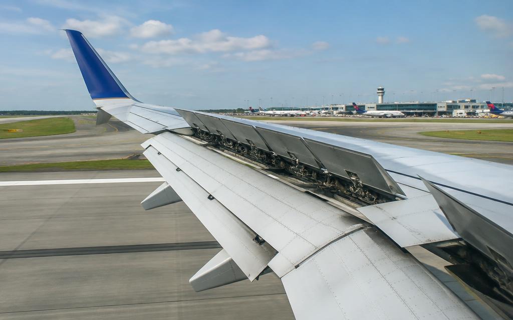
Wing with winglet, spoilers, flaps and leading-edge devices
Wing with winglet, spoilers, flaps and leading-edge devices · illustrative image

Swept wing with leading edge slats and Krueger flaps, triple-slotted trailing edge flaps, spoilers, and winglets.

  • Ailerons are powered by Systems A and B; aileron movement is assisted by flight spoilers.
  • Flap lever settings: 1, 2, 5, 10, 15, 25, 30, 40. Trailing edge flaps driven hydraulically by System B (electric alternate).
  • Leading edge devices: Krueger flaps inboard, slats outboard; Autoslat function extends slats near stall.
  • Fuel in two main wing tanks and a center tank.

Landing Gear ATA 29, 32

Where it is

Location of Landing Gear
Landing Gear

What it looks like

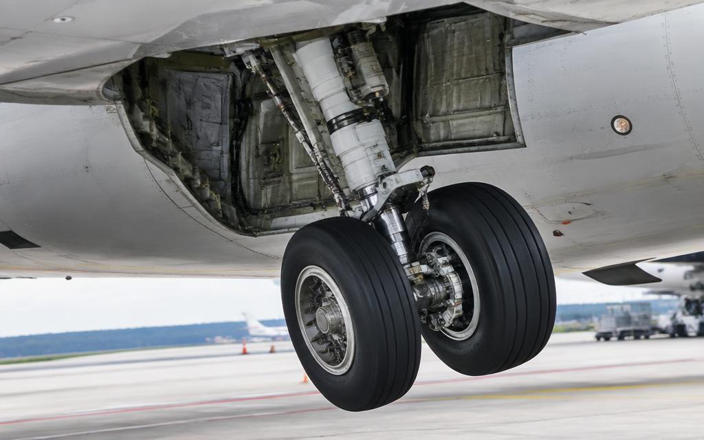
Main gear and open wheel well (no main gear doors on the 737)
Main gear and open wheel well (no main gear doors on the 737) · illustrative image

Retractable tricycle gear powered by System A hydraulics; main gear retracts into wheel wells without doors.

  • Gear lever UP/OFF/DN; manual extension via three handles that release uplocks so gear free-falls.
  • Main gear wheels are exposed in flight — fairings seal around the tires instead of doors.
  • Brakes: normal System B, alternate System A, with accumulator for parking brake.
  • Autobrake RTO, 1, 2, 3, MAX; anti-skid on each wheel.

Fuselage, Air & Electrical ATA 21, 24, 25, 52, 53

Where it is

Location of Fuselage, Air & Electrical
Fuselage, Air & Electrical

Narrow fuselage (same cross-section as the 707/727) with two packs and a digital pressurization controller.

  • Bleed air drives two air conditioning packs; recirculation fans mix cabin air.
  • Pressurization: AUTO, ALTN and MAN modes controlling one outflow valve; max differential 9.1 psi.
  • Electrical: two IDGs and APU generator; transfer buses with bus tie; 28 V DC from TRUs; standby power from main battery.
  • Forward and aft cargo holds with smoke detection and fire suppression.

Empennage & APU ATA 49, 55

Where it is

Location of Empennage & APU
Empennage & APU

What it looks like

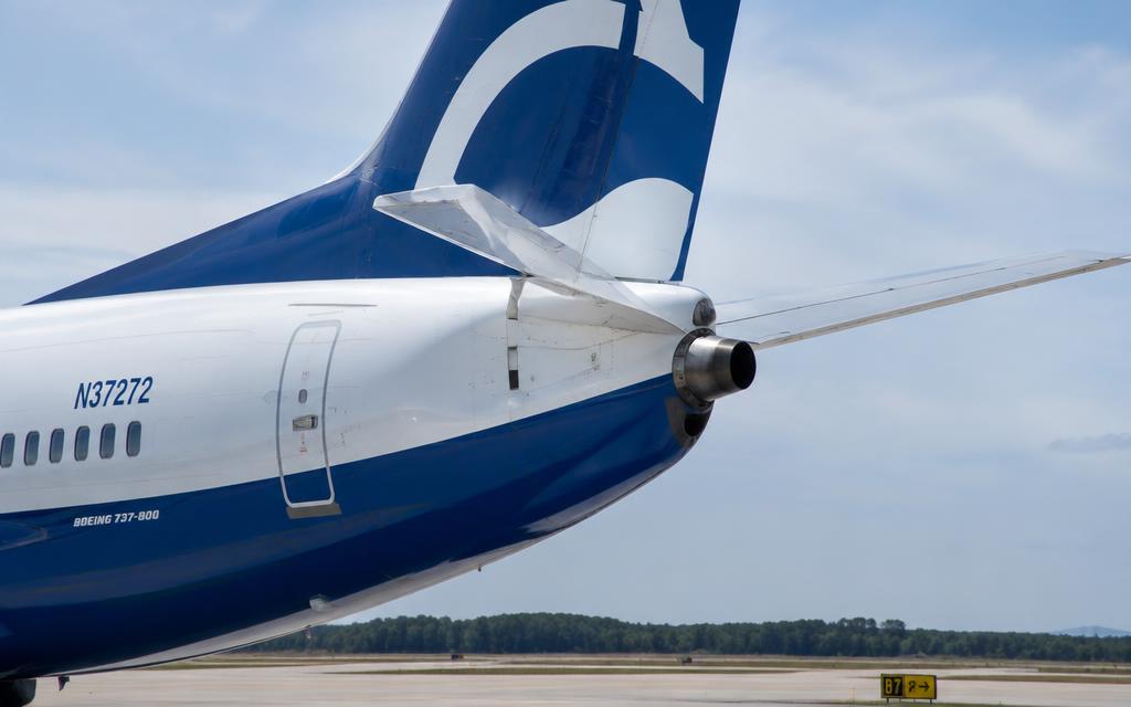
Tail with APU exhaust, rudder and stabilizer
Tail with APU exhaust, rudder and stabilizer · illustrative image

Stabilizer trim with electric and manual (trim wheels) operation, elevators, rudder, and APU in the tail.

  • Stabilizer trim: main electric (yoke switches), autopilot trim, and manual trim wheels; STAB TRIM CUTOUT switches disconnect electric trim.
  • Elevators powered by Systems A & B with manual reversion through tabs.
  • Rudder powered by A & B plus a standby rudder PCU.
  • APU (Honeywell 131-9B) provides bleed and electrical power.
7A

Annunciators & Fault Messages

Open the interactive fault finder →

LOW OIL PRESSUREOil pressure at or below the red line.
HYD PUMP LOW PRESSURE (A)Output pressure of a system A pump low.
BLEED TRIP OFFEngine bleed overheat or overpressure — bleed valve closed automatically.
AUTO FAIL (pressurization)Automatic pressurization controller failure.
TRANSFER BUS OFFA transfer bus has lost power.
STAB OUT OF TRIMAutopilot is not trimming the stabilizer properly.
ENGINE FIRE / SEVERE DAMAGE / SEPARATIONFire bell, master FIRE WARN lights, engine fire handle illuminated.
RUNAWAY STABILIZERUncommanded continuous stabiliser trim movement.
CABIN ALTITUDE WARNING / RAPID DEPRESSURIZATIONIntermittent horn and CABIN ALTITUDE light — cabin altitude above about 10,000 ft.
LOSS OF THRUST ON BOTH ENGINESBoth engines flamed out or failed.
AIRSPEED UNRELIABLEIAS DISAGREE / ALT DISAGREE or incorrect indications.
ENG OVERHEATOverheat detected in the engine nacelle — lower temperature than fire.
FUEL LOW / IMBALMain tank fuel below about 453 kg, or imbalance more than about 453 kg between mains.
GEAR DISAGREEGear position disagrees with lever position.
Tail strike on takeoff / landingAft fuselage contacted the runway. The -800 and -900 have a tail skid; possible pressure-hull damage.
Dual BLEED TRIP OFFBoth engine bleeds tripped: no supply to the packs, cabin will depressurise.
PACK (L/R) trip offPack overheat — the pack valve closes.
Trailing edge flap asymmetry / disagreeFlap position needles split, or flaps stop. Hydraulic drive shuts off to protect the aircraft.
STANDBY PWR OFFOne or more standby buses unpowered. Standby instruments and essential radios at risk.
GPWS 'TERRAIN — PULL UP'Enhanced GPWS predicts terrain conflict. Escape manoeuvre immediately.
7B

Systems In Depth (engine, gear, controls…)

Deep dive · ATA 21

Air Conditioning & Pressurisation — in depth

Packs & zones

Two packs (air cycle machines) in the wheel well area. Each pack takes bleed air via the pack valve; outlet air goes to the mix manifold, with recirculation fans. NG has three temperature zones (flight deck, forward and aft cabin) with trim air.

PACK switch AUTO/HIGH: in AUTO, high flow only when one pack operates in flight with flaps up.

Pressurisation

Two automatic controllers (AUTO and ALTN) and a MAN mode drive the outflow valve (aft fuselage, lower right) plus an overboard exhaust valve. The pilot sets FLT ALT and LAND ALT on the pressurisation panel before takeoff.

Safety relief valves limit differential to about 8.65 psi; negative relief prevents inward pressure.

Max differential8.35 psi normal, 8.65 relief
Cabin altitude at FL410approx. 8 000 ft
CABIN ALTITUDE warning10 000 ft (intermittent horn)
Masks deploy automaticallyapprox. 14 000 ft cabin

Lessons — Helios 522

The pressurisation mode selector was left in MAN after maintenance; the outflow valve stayed open. The cabin altitude warning horn was misidentified as a takeoff configuration warning. Lesson: always check the pressurisation panel on the before-start checklist and react to the cabin altitude warning with oxygen masks first.

Warning · Intermittent warning horn in climb = cabin altitude. Masks on, establish communication, descend.

Deep dive · ATA 22

Auto Flight — AFDS, A/T and FMC in depth

Components

Two flight control computers (FCC A, B) driving the autopilot servos (CMD A / CMD B), the Mode Control Panel (MCP), the autothrottle computer, and two FMCs with CDUs. On the MAX the FCC also hosts MCAS logic.

Roll modesLNAV, HDG SEL, VOR/LOC, APP
Pitch modesVNAV, LVL CHG, V/S, ALT HOLD, G/S, TO/GA
A/T modesN1, MCP SPD, FMC SPD, RETARD, ARM, THR HLD
AutolandDual channel (CMD A + B) — FLARE, ROLLOUT

Disconnect logic

Autopilot disconnects with the yoke button, MCP disengage bar, or forcing the controls (CWS override on some). Autothrottle disconnects with buttons on the thrust levers. Disconnect warnings: flashing red A/P light and wailer; flashing red A/T light.

Deep dive · ATA 24

Electrical Power — in depth

Generation

Two IDGs (90 kVA, 115 V 400 Hz), one APU generator (90 kVA, usable on ground and in flight), external power. DC via three TRs (TR1, TR2, TR3) and a main battery (plus an auxiliary battery on NG). A static inverter supplies the AC standby bus from the battery.

IDG90 kVA each
APU GEN90 kVA
TRs3
Battery standby timeapprox. 30–60 min (aux battery fitted)

Bus logic (NG)

The NG uses a 'split system' with automatic Bus Transfer: each generator normally powers its own transfer bus; if one source fails, the BUS TRANSFER switch in AUTO lets the opposite generator pick up the transfer bus. The pilot connects generators by momentary GEN 1/2 switches on the overhead — the new source disconnects the old one ('break before make').

Standby power: with all AC lost, the battery powers the hot battery bus, battery bus, DC standby bus and, through the static inverter, AC standby bus — flight instruments, one radio, standby compass lighting.

Indications

TRANSFER BUS OFFTransfer bus unpowered
SOURCE OFFNo source selected for the transfer bus
GEN OFF BUSIDG not supplying the bus
DRIVEIDG low oil pressure (disconnect per checklist)
STANDBY PWR OFFAC/DC standby bus unpowered

Warning · IDG disconnect is irreversible in flight. Hold the switch only as long as the checklist states.

Deep dive · ATA 26

Fire Protection — in depth

Detection

Engines: two overheat/fire detector loops (A and B) per engine; the OVHT DET switch selects NORMAL (both loops, AND logic), A or B. APU: single loop. Main wheel well: fire detector loop. Cargo compartments: dual smoke detectors. Lavatories: smoke detector and waste bin extinguisher.

Extinguishing

Two engine fire bottles shared between both engines — each bottle can discharge into either engine (left or right rotation of the fire handle). One APU bottle. Cargo fire bottle with a high-rate and a metered (low-rate) discharge for extended diversion.

Pulling the engine fire handle closes the engine fuel valve, bleed valve, hydraulic shutoff and disconnects the generator, and arms the bottle squibs; rotating it discharges.

Engine bottles2 (shared)
APU bottle1
Cargo1 bottle (dual discharge)
TestFAULT/INOP and OVHT/FIRE test switch on the fire panel

Engine fire (outline)

  1. 1.Autothrottle disengage.
  2. 2.Thrust lever (affected) close.
  3. 3.Start lever (affected) CUTOFF.
  4. 4.Engine fire handle pull.
  5. 5.Rotate to the stop and hold 1 s.
  6. 6.If after 30 s the fire light is still on: rotate to the other stop.

Warning · Teaching outline only — use the approved QRH.

Deep dive · ATA 27

Flight Controls — in depth

Primary controls

Conventional cable-driven controls powered by hydraulic power control units (PCUs). Roll is by ailerons assisted by flight spoilers; pitch by elevators with a moving horizontal stabilizer for trim; yaw by a single rudder.

The stabilizer is moved by a jackscrew driven by an electric trim motor (main electric trim / autopilot) or by the cockpit trim wheels through cables.

Speed trim & MCAS

Speed Trim System (STS) automatically trims the stabilizer at low speed/high thrust to improve speed stability. On the 737 MAX, MCAS adds nose-down stabilizer at high angle of attack with flaps up. Since 2020 MCAS compares both AoA sensors, activates only once per event and is limited in authority.

Warning · Runaway stabilizer: hold the control column firmly, autopilot and autothrottle disengage, STAB TRIM CUTOUT switches to CUTOUT, then trim manually with the wheel.

Deep dive · ATA 28

Fuel System — in depth

Tanks & pumps

Main tank 1 (left wing), main tank 2 (right wing), centre tank in the wing-box and fuselage. Each main tank has two AC boost pumps (FWD and AFT); the centre tank has two override/jettison-style pumps with higher output pressure so centre fuel is used first.

A cross-feed valve connects the left and right manifolds. If all pumps fail, suction feed from the main tanks is possible at lower altitudes.

Total usable (NG)approx. 26 000 L / approx. 20 800 kg
Main tanks (each)approx. 3 900 kg
Centre tankapprox. 13 000 kg
Fuel temp minimum3 °C above freezing point / −43 °C

Operating rules

Centre tank pumps ON when centre tank contains more than about 453 kg; OFF when LOW PRESSURE lights illuminate. Main tanks must be full if centre tank contains fuel (structural rule).

Imbalance: the FUEL IMBALANCE alert shows on EICAS/upper display when the main tanks differ by more than about 453 kg.

Warning · Never run centre tank pumps dry with low pressure lights on — risk of pump overheating and fuel-vapour ignition (see TWA 800 / SFAR 88).

Maintenance

Sump drainingDaily per MPD
Measuring sticksDrip sticks under the wing for manual quantity
Pump replacementCanister type — can be changed without draining the tank

Deep dive · ATA 29

Hydraulics — in depth

Systems

System AEngine 1 EDP + electric motor-driven pump (EMDP). Ailerons, rudder, elevators, spoilers, gear, NWS, alternate brakes, reverser 1
System BEngine 2 EDP + EMDP. Flight controls, flaps/slats, normal brakes, autobrake, yaw damper, reverser 2
StandbyElectric pump. Backup rudder, LE devices (full extend), reversers
Pressure3000 psi
ReservoirsPressurised by bleed air

Manual reversion

If both A and B fail, ailerons and elevators are flown mechanically through cables and servo tabs ('manual reversion') — heavy but controllable. Rudder is powered by the standby system. Flaps can be extended electrically (alternate flaps).

Deep dive · ATA 30

Ice & Rain Protection — in depth

Systems

Wing anti-ice: bleed air to the three inboard leading-edge slats (NG) per wing; on the ground the valves close automatically at takeoff thrust (thrust lever/air-ground logic). Engine anti-ice: cowl valves per engine. Window heat for the flight-deck windows, probe heat for pitot, AOA vanes, TAT. Wipers per side.

Warning · Engine anti-ice must be ON in icing conditions on the ground and in flight, including descent, before entering icing, not after ice accretes.

Deep dive · ATA 32

Landing Gear — in depth

Configuration

Tricycle with twin wheels. Main gear retracts inboard into wheel wells with no doors — the outer side of the tyre stays exposed in flight and forms part of the fuselage contour, sealed by brush seals. The nose gear retracts forward into a doored well.

Normal operation from hydraulic system A. If A fails, gear retraction can come from system B through the landing gear transfer unit (when engine 1 N2 drops below a threshold).

Main tyresH44.5 × 16.5-21, approx. 205 psi
Nose tyres27 × 7.75-15, approx. 190 psi
VLO extension270 kt / M 0.82
VLO retraction235 kt
VLE320 kt / M 0.82

Manual extension

Three T-handles in a floor hatch behind the first officer's seat release the uplocks for right main, nose and left main. Each gear free-falls and locks with gravity and air load. Pull each handle up to about 24 in.

Brakes & autobrake

Normal brakesHydraulic system B with anti-skid
Alternate brakesSystem A with anti-skid
AccumulatorSeveral applications if both lost; parking brake source
AutobrakeRTO, 1, 2, 3, MAX — deceleration from approx. 4 ft/s² to 14 ft/s²
Carbon or steel brakesCarbon on most NG; brake temperature monitoring shows 0–9 scale

Nose wheel steering

Tiller ±78°, rudder pedals ±7°. Hydraulic system A normally; system B as alternate when the NOSE WHEEL STEERING switch is set to ALT. A towing lever on the nose gear depressurises steering for pushback.

Deep dive · ATA 34

Navigation & Avionics — in depth

ADIRS

Two ADIRUs (left and right), each combining air data (from the pitot-static probes through ADMs) and an inertial reference system with ring-laser gyros. Mode selector OFF/ALIGN/NAV/ATT; alignment about 10 minutes. An IRS can be used in ATT mode in flight (attitude only) after a nav failure.

Common Display System

Six identical displays: outboard (PFD), inboard (ND), upper centre (engine primary / EICAS-like) and lower centre (secondary engine / systems). Two Display Electronics Units (DEU). Source selectors on the forward panel switch display sources if a unit fails.

Radio navigation & surveillance

VHF NAV2 multi-mode receivers (VOR/ILS/GLS)
DME2
ADF1–2
Radio altimeters2
GPS2 (integrated in MMR)
SurveillanceTCAS II, Mode S transponders, EGPWS, predictive windshear radar

Deep dive · ATA 36

Pneumatic — in depth

Sources & ducting

Bleed air comes from the 5th stage (normal) and 9th stage (low power) of the CFM56-7B HP compressor, through the PRSOV and precooler. The APU and ground air connectors also feed the manifold. An isolation valve separates left and right ducts (AUTO opens it if one bleed or pack is off).

Duct pressure normalapprox. 30–45 psi
BLEED TRIP OFFOver-temperature/over-pressure — reset after cooling
WING-BODY OVERHEATDuct leak detected — isolate
DUAL BLEEDAPU and engine bleed both open — thrust limit

Deep dive · ATA 49

APU — in depth

Construction

Honeywell 131-9B (NG) gas turbine in the tail cone. Electronic Control Unit (ECU) controls start, governing and protective shutdowns. Fuel from the left main fuel manifold (no separate APU tank). Air inlet door on the right side of the tail.

Generator90 kVA (ground and flight)
Bleed useUp to approx. 17 000 ft
Electrical useUp to 41 000 ft
Start: 3-position switchOFF / ON / START (spring to ON)

Indications

MAINTMaintenance problem — APU usable
LOW OIL PRESSUREAuto shutdown (except during start)
FAULTAuto shutdown — cause recorded in the ECU
OVERSPEEDAuto shutdown

Deep dive · ATA 72

Engines — CFM56-7B (and LEAP-1B on MAX)

Engine architecture

Two-spool high-bypass turbofan: fan + 3-stage booster on N1 driven by 4-stage LPT; 9-stage HPC on N2 driven by a single-stage HPT. Bypass ratio about 5.1–5.5 : 1.

The engine is mounted forward and high on the wing. Because the 737 sits low to the ground, the nacelle has a flattened lower lip (the 'hamster pouch') to fit the larger fan; accessories are moved to the sides of the fan case.

Thrust19,500–27,300 lbf
Fan diameter61 in
N1 redline104 %
N2 redline105 %
EGT redline takeoff950 °C
EGT start limit725 °C
Oil capacity (tank)approx. 20 qt usable

EEC (FADEC)

Dual-channel Electronic Engine Control in NORMAL mode schedules N1 from the thrust lever angle corrected for altitude, temperature and bleed. If required inputs are lost it reverts to ALTERNATE mode (soft or hard), where N1 is less precise and protection is reduced — thrust levers should be retarded before selecting ALTN.

Ground start sequence

  1. 1.Bleed air available (APU bleed ON, isolation valve AUTO/OPEN), packs OFF for maximum duct pressure (approx. 30 psi minimum at sea level).
  2. 2.ENGINE START switch to GRD: start valve opens, starter drives N2. Oil pressure rises.
  3. 3.At 25% N2 (or max motoring) — start lever to IDLE: igniters fire, fuel flows.
  4. 4.Watch EGT rise (light-off within 10 s) and stay within limits.
  5. 5.At 56% N2: start switch releases to OFF automatically, the start valve closes. Stabilised idle about 60% N2.

Warning · Abort the start for no EGT rise within 10 s, EGT rapidly approaching 725 °C, no N1 rotation by 40% N2, or no oil pressure.

Thrust reversers

Cascade type, translating sleeves. Engine 1 reverser from hydraulic system A, engine 2 from system B, with standby system backup. Reverse can only be selected with thrust levers at idle and the aircraft on the ground (radio altimeter < 10 ft or air/ground sensing).

8A

Maintenance Task Cards

Recirculation filter replacement

ATA 21 · Per MPD (approx. 4 000–6 000 FH)

Access · Forward cargo / mix bay

Tools & materials · Gloves · Mask · Bags for disposal

Warning · Wear protective mask and gloves when handling used filters.

  1. 1.Electrical power off for recirculation fans (open breakers, tag).
  2. 2.Remove the filter housing cover and old HEPA filter.
  3. 3.Bag the old filter (may contain biological contamination).
  4. 4.Install the new filter with arrow in flow direction; close cover; close breakers; run fans.
Filter typeHEPA, part number per IPC

Ref: B737 AMM 21-25-00

IDG oil level check & servicing

ATA 24 · Per MPD

Access · Left fan cowl

Tools & materials · IDG servicing cart · Approved oil

  1. 1.Engine shut down 5 min minimum.
  2. 2.Open fan cowl; read the IDG sight gauge.
  3. 3.Service with pressure fill until oil flows from the overflow.
  4. 4.Check filter delta-P indicator; close cowls.
OilMIL-PRF-23699

Ref: B737 AMM 24-11-00

Engine fire detection & extinguishing test

ATA 26 · Preflight (crew) / per MPD (maint.)

Access · Flight deck fire panel

Tools & materials · None

  1. 1.Hold FAULT/INOP test switch: check FAULT, APU DET INOP, MASTER CAUTION and OVHT/DET annunciators.
  2. 2.Hold OVHT/FIRE test: fire bell, fire handles, wheel well light, MASTER FIRE WARN, ENG OVERHEAT lights.
  3. 3.Press EXTINGUISHER TEST 1 and 2: three green squib lights per test.
  4. 4.Check bottle pressures (maintenance) against chart.
All test lightsMust illuminate

Ref: B737 AMM 26-11-00 / FCOM SP

Stabilizer trim jackscrew lubrication

ATA 27 · Per MPD (approx. C-check / 1800–3600 FH)

Access · Aft equipment area, stabilizer compartment

Tools & materials · Approved grease (e.g. Aeroshell 33) · Grease gun · Torque check tooling

Warning · Lack of lubrication on a stab trim screw has caused fatal accidents (e.g. Alaska 261 on an MD-83).

  1. 1.Remove access panels to the jackscrew.
  2. 2.Clean old grease from the screw threads.
  3. 3.Apply new grease and run the stabilizer full travel to distribute.
  4. 4.Check the end play of the ballnut against the limit.
  5. 5.Reinstall panels; operational test of main electric and manual trim.
Ballnut end playAMM limit (wear indicator)

Ref: AMM 12-21-27 / MPD

Fuel tank sump drain

ATA 28 · Daily / per MPD

Access · Under each wing and centre tank

Tools & materials · Drain tool · Sample jar

  1. 1.Allow fuel to settle.
  2. 2.Drain each main and centre tank sump until clear.
  3. 3.Check for water and microbial contamination (dark slime).
  4. 4.Close and check for leaks; record.
Free waterNone after draining

Ref: B737 AMM 12-11-28

Tyre pressure & wheel inspection

ATA 32 · Daily

Access · Gear on ground

Tools & materials · Calibrated gauge · Nitrogen

Warning · Never stand in line with the wheel axle.

  1. 1.Check cold tyres; correct to placard.
  2. 2.Look for cuts, bulges, worn tread to the bottom of a groove.
  3. 3.Check thermal fuse plugs and wheel tie bolts.
  4. 4.Record and remove per loss limits (same as 5 % / 10 % rule).
Max daily loss5 %

Ref: AMM 12-15-31

APU oil level check

ATA 49 · Daily / per MPD

Access · APU access door (left side tail cone)

Tools & materials · Approved oil

  1. 1.APU off (wait as specified).
  2. 2.Read the oil sight gauge; LOW OIL QUANTITY indication on the upper display.
  3. 3.Service to FULL via gravity fill.
  4. 4.Close door; record quantity added (trend monitoring).
OilMIL-PRF-23699

Ref: B737 AMM 12-13-49

HPT borescope inspection

ATA 72 · Per EGT margin / bird strike / every A-check per program

Access · Borescope ports on core case

Tools & materials · Video borescope · Core rotation tool (N2 drive pad)

  1. 1.Engine cooled; install the manual turning tool on the AGB.
  2. 2.Insert borescope through the HPT port.
  3. 3.Rotate N2 and inspect each blade for burns, cracks, coating loss, tip curl.
  4. 4.Measure damage against AMM limits; record images.
  5. 5.Remove tools, install port plugs with torque and safety.
Tip erosion / burnwithin AMM-defined zones

Ref: AMM 72-00-00 Inspection/Check

Engine oil servicing (CFM56-7B)

ATA 79 · Daily / as required

Access · Right side fan cowl oil fill door

Tools & materials · Approved oil · Lint-free cloth

Warning · A cap not locked can cause total oil loss in flight.

  1. 1.Service within 30 min of shutdown for an accurate reading (or after motoring the engine).
  2. 2.Open the oil filler access; read sight gauge.
  3. 3.Remove the cap slowly, fill to FULL.
  4. 4.Install cap — check the locking handle is fully down and flush.
  5. 5.Record quantity for consumption trend.
Usable tankapprox. 20 qt

Ref: AMM 12-13-11

8

Maintenance Overview (by ATA)

ATA 21 — Air Conditioning & Pressurization

  • Door seal, escape slide and emergency equipment checks.
  • Lap joint and skin corrosion inspections per ALS / SSID.
  • Pack and heat exchanger maintenance per MPD.

ATA 22 — Auto Flight

  • ADIRU and FCC BITE tests per AMM Chapter 22/34.
  • Pitot-static leak checks and probe heat tests.
  • CDS software part numbers verified against configuration.

ATA 23 — Communications

  • ADIRU and FCC BITE tests per AMM Chapter 22/34.
  • Pitot-static leak checks and probe heat tests.
  • CDS software part numbers verified against configuration.

ATA 24 — Electrical Power

  • Door seal, escape slide and emergency equipment checks.
  • Lap joint and skin corrosion inspections per ALS / SSID.
  • Pack and heat exchanger maintenance per MPD.

ATA 25 — Equipment / Furnishings

  • Door seal, escape slide and emergency equipment checks.
  • Lap joint and skin corrosion inspections per ALS / SSID.
  • Pack and heat exchanger maintenance per MPD.

ATA 26 — Fire Protection

  • Engine oil quantity check at each daily/transit; consumption trending.
  • Borescope inspections per CFM ESM / MPD; fan blade lubrication.
  • Thrust reverser functional and lockout checks per AMM 78.

ATA 27 — Flight Controls

  • Flap track and carriage lubrication and wear checks per MPD.
  • Inspect winglets and leading edges for damage.
  • Fuel sump drains and water checks per operator schedule.

ATA 28 — Fuel

  • Flap track and carriage lubrication and wear checks per MPD.
  • Inspect winglets and leading edges for damage.
  • Fuel sump drains and water checks per operator schedule.

ATA 29 — Hydraulic Power

  • Tire pressure and brake wear pin checks daily.
  • Strut servicing (nitrogen/fluid) per AMM 12/32.
  • Gear swing / retraction tests per MPD.

ATA 30 — Ice & Rain Protection

  • Flap track and carriage lubrication and wear checks per MPD.
  • Inspect winglets and leading edges for damage.
  • Fuel sump drains and water checks per operator schedule.

ATA 31 — Indicating / Recording

  • ADIRU and FCC BITE tests per AMM Chapter 22/34.
  • Pitot-static leak checks and probe heat tests.
  • CDS software part numbers verified against configuration.

ATA 32 — Landing Gear

  • Tire pressure and brake wear pin checks daily.
  • Strut servicing (nitrogen/fluid) per AMM 12/32.
  • Gear swing / retraction tests per MPD.

ATA 34 — Navigation

  • ADIRU and FCC BITE tests per AMM Chapter 22/34.
  • Pitot-static leak checks and probe heat tests.
  • CDS software part numbers verified against configuration.

ATA 35 — Oxygen

  • ADIRU and FCC BITE tests per AMM Chapter 22/34.
  • Pitot-static leak checks and probe heat tests.
  • CDS software part numbers verified against configuration.

ATA 36 — Pneumatic

  • Engine oil quantity check at each daily/transit; consumption trending.
  • Borescope inspections per CFM ESM / MPD; fan blade lubrication.
  • Thrust reverser functional and lockout checks per AMM 78.

ATA 49 — Airborne Auxiliary Power (APU)

  • Stabilizer jackscrew lubrication and end-play checks — critical item per MPD.
  • APU oil and fire detection tests.
  • Elevator tab free-play checks.

ATA 52 — Doors

  • Door seal, escape slide and emergency equipment checks.
  • Lap joint and skin corrosion inspections per ALS / SSID.
  • Pack and heat exchanger maintenance per MPD.

ATA 53 — Fuselage

  • Door seal, escape slide and emergency equipment checks.
  • Lap joint and skin corrosion inspections per ALS / SSID.
  • Pack and heat exchanger maintenance per MPD.

ATA 55 — Stabilizers

  • Stabilizer jackscrew lubrication and end-play checks — critical item per MPD.
  • APU oil and fire detection tests.
  • Elevator tab free-play checks.

ATA 57 — Wings

  • Flap track and carriage lubrication and wear checks per MPD.
  • Inspect winglets and leading edges for damage.
  • Fuel sump drains and water checks per operator schedule.

ATA 71 — Power Plant

  • Engine oil quantity check at each daily/transit; consumption trending.
  • Borescope inspections per CFM ESM / MPD; fan blade lubrication.
  • Thrust reverser functional and lockout checks per AMM 78.

ATA 72 — Engine

  • Engine oil quantity check at each daily/transit; consumption trending.
  • Borescope inspections per CFM ESM / MPD; fan blade lubrication.
  • Thrust reverser functional and lockout checks per AMM 78.

ATA 73 — Engine Fuel & Control

  • Engine oil quantity check at each daily/transit; consumption trending.
  • Borescope inspections per CFM ESM / MPD; fan blade lubrication.
  • Thrust reverser functional and lockout checks per AMM 78.

ATA 74 — Ignition

  • Engine oil quantity check at each daily/transit; consumption trending.
  • Borescope inspections per CFM ESM / MPD; fan blade lubrication.
  • Thrust reverser functional and lockout checks per AMM 78.

ATA 78 — Exhaust / Thrust Reverser

  • Engine oil quantity check at each daily/transit; consumption trending.
  • Borescope inspections per CFM ESM / MPD; fan blade lubrication.
  • Thrust reverser functional and lockout checks per AMM 78.

ATA 79 — Oil

  • Engine oil quantity check at each daily/transit; consumption trending.
  • Borescope inspections per CFM ESM / MPD; fan blade lubrication.
  • Thrust reverser functional and lockout checks per AMM 78.

EDUCATIONAL USE ONLY. Content is summarised from manufacturer documentation for learning. It is not approved flight or maintenance data. Always use the current, aircraft-specific POH/AFM, FCOM, QRH, AMM and operator procedures.