Sections menu
Boeing 737-800 NG · Live schematics
System schematics
Operate the switches and introduce failures — the diagram shows where fuel, power or pressure flows and what it means for the pilot.
Unverified — check your manualText on this page is written from general knowledge. Figures marked ✓ are checked against official FAA/EASA data.See verified data
ATA 29 Hydraulic Power · Systems A and B each have an engine-driven pump and an electric pump; the standby system backs up rudder, leading edge devices and thrust reversers.
Where it is
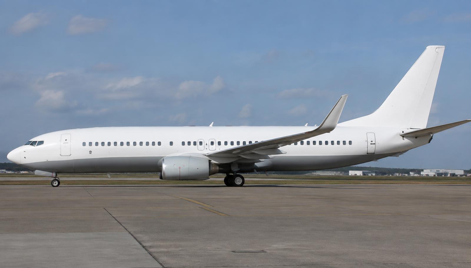
Hydraulic System (A / B / Standby)
What it looks like
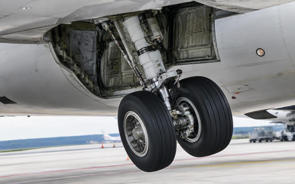
Controls
Engine 1
Engine 2
ELEC 2 (A)
ELEC 1 (B)
FLT CONTROL STBY RUD
Inject failures
What this means
- Both main systems pressurised.
How it works
- Systems A and B each have one engine-driven pump and one electric pump at 3,000 psi.
- System A: engine 1 pump plus electric pump 2. System B: engine 2 pump plus electric pump 1 — crossed for redundancy.
- The standby system has an electric pump and powers the rudder, leading edge devices and reversers.
- If A and B are both lost, the ailerons and elevators work by manual reversion (cables).
How the parts work together
- A and B both power the flight controls, so either alone can fly the aircraft.
- The PTU uses A to drive B's autoslats; LETS can retract the gear with B.
- Standby activates automatically or by switch.
What each part does
Click a box in the diagram or a part below to highlight it.
EDUCATIONAL USE ONLY. Content is summarised from manufacturer documentation for learning. It is not approved flight or maintenance data. Always use the current, aircraft-specific POH/AFM, FCOM, QRH, AMM and operator procedures.