Back to dashboard
Sections menu

Lockheed Martin C-130J Super Hercules · Maintenance

Maintenance & fault isolation

Inspection programme by ATA chapter and step-by-step troubleshooting trees, in the style of an AMM / FIM.

Unverified — check your manualText on this page is written from general knowledge. Figures marked ✓ are checked against official FAA/EASA data.See verified data

Inspection programme

WhereIntervalATATaskReference
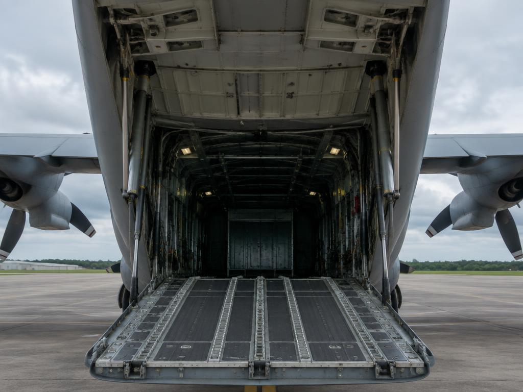
Rear cargo ramp and upper door with actuators
Before each flight (preflight)05Exterior walkaround: props (blade damage, de-ice boots), nacelles for leaks, gear and tyres in sponsons, ramp/door seals, static ports and probes, fluid levelsC-130J Flight Manual / preflight requirements
Rear cargo ramp and upper door with actuators
Thru-flight (between sorties)05Walkaround, oil/hydraulic levels, tyre and brake wear pins, ACAWS and maintenance fault history review on the MFDsThru-flight inspection workcards
Rear cargo ramp and upper door with actuators
Basic post-flight / daily05Detailed post-flight: engine oil and gearbox levels, prop oil, hydraulic reservoirs (utility, booster, auxiliary), oxygen quantity, cargo floor and railsBasic post-flight workcards
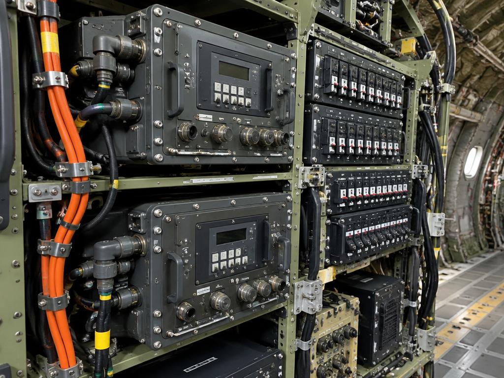
Maintenance data and avionics racks
Each flight (data)45Download the integrated diagnostics data (DTD) and review engine trend, propeller and avionics fault logsIntegrated diagnostics / AMM 45
Rear cargo ramp and upper door with actuators
Home-station check (approx. 180 days)05Scheduled inspection of airframe, flight controls, landing gear, ramp actuators and lubrication of hinges and rollersScheduled inspection requirements
Rear cargo ramp and upper door with actuators
Isochronal / phased inspection05Major phased inspection: panels off, structural inspection of wing, empennage and fuselage, corrosion control, systems ops checksPhased/isochronal inspection package
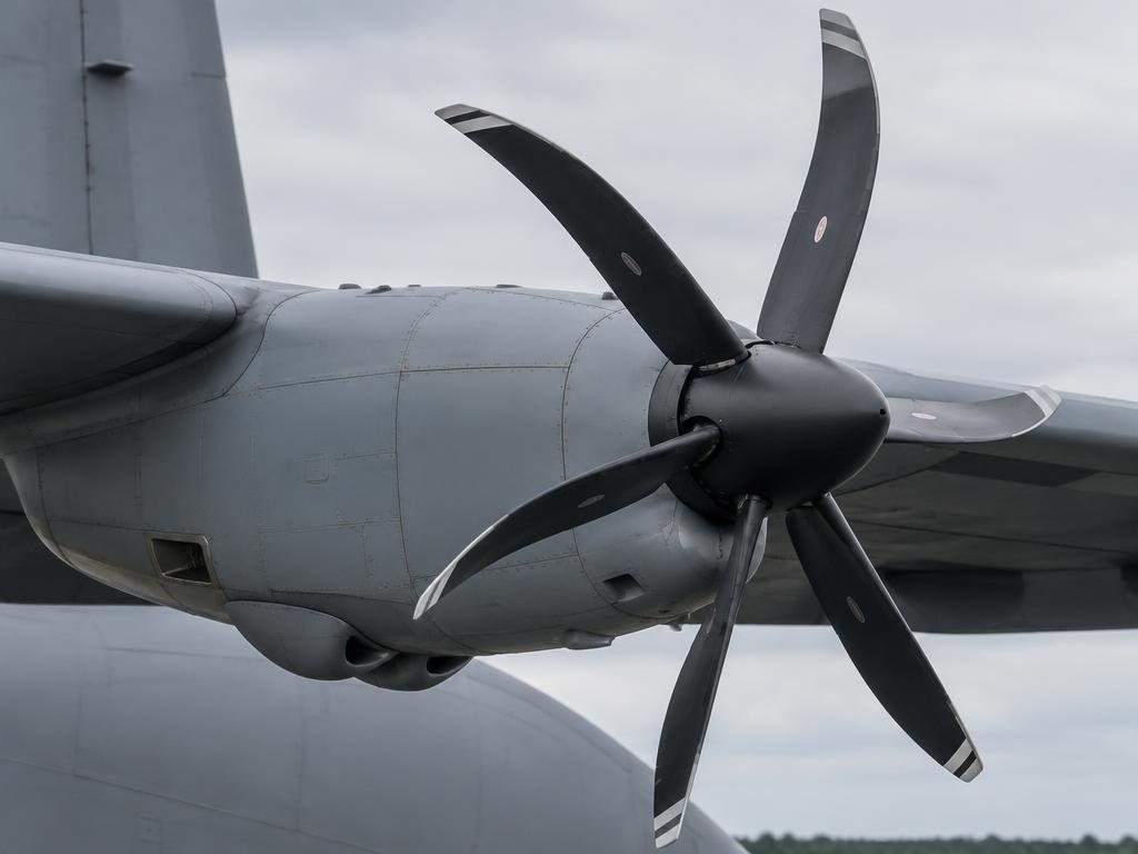
Six-blade composite R391 propeller
Scheduled61R391 propeller: blade erosion and delamination, de-ice heater check, propeller electronic control (EPC) BIT, pitch-change oil levelPropeller CMM / AMM 61
Turboprop engine in its nacelle
On condition / trend72AE 2100D3 borescope of compressor and turbine; engine condition trend monitoring (ITT, torque, Np margins)Rolls-Royce AE 2100D3 engine manual
Turboprop engine in its nacelle
Scheduled72Reduction gearbox chip detectors and oil filter inspectionAMM 72
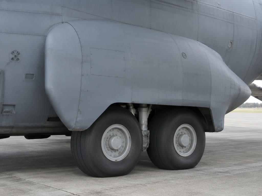
Tandem main wheels in the sponson
Scheduled32Main gear tandem struts, screwjack retraction mechanism, torque tubes, brakes and antiskid wiring; nose gear steeringAMM 32
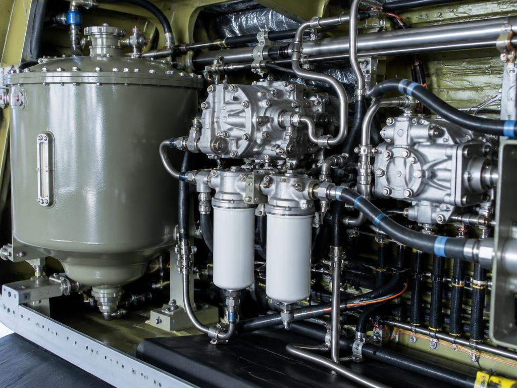
Hydraulic reservoir, pumps and filters
Scheduled29Hydraulic pumps, accumulators, filters (differential pressure indicators) and leak checks on utility, booster and auxiliary systemsAMM 29
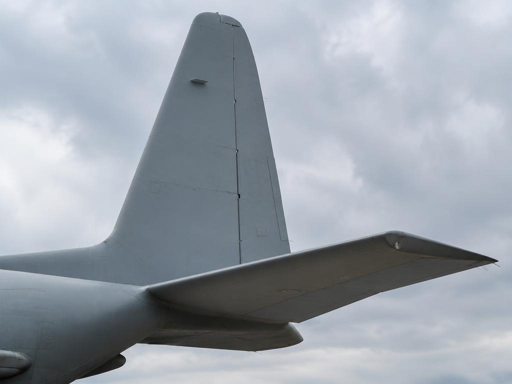
Fin, rudder, stabiliser and elevator
Scheduled27Elevator and rudder booster packs, aileron booster, trim tabs and control cable tension checkAMM 27
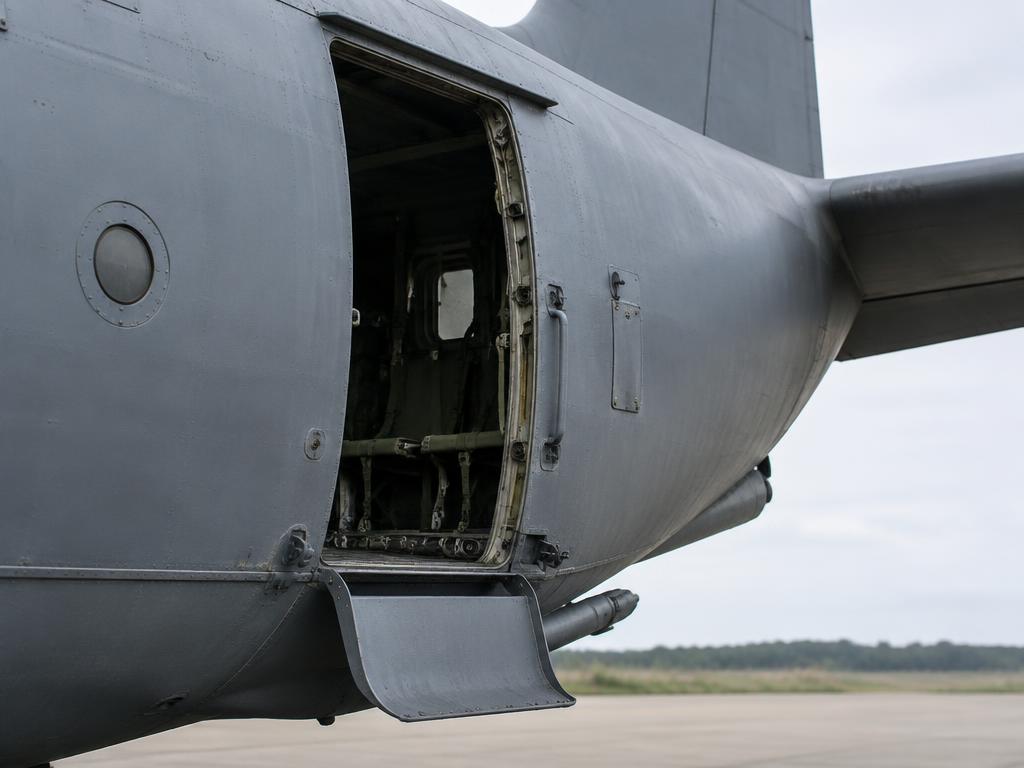
Side paratroop door with air deflector
Scheduled52Cargo ramp and door: hinges, locks, actuators, seals, paratroop doors and crew entrance doorAMM 52
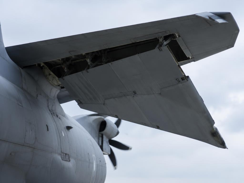
Wing box with flaps and ailerons
Scheduled57Wing centre box and outer wing structural inspection, fuel tank sealant and corrosion around the wing jointsAMM 57 / structural inspection
Engine nacelle - fire detection and extinguishing
Scheduled26Fire detection loops test, fire bottle weight/pressure and squib checkAMM 26
Scheduled35Crew and troop oxygen system: LOX/gaseous quantity, masks, regulators and leak checkAMM 35

Task cards

Step-by-step maintenance tasks with access, tools, limits and warnings — in the style of an AMM task card.

Main Battery Voltage and Security Check

ATA 24 · Weekly / Before flight

Access · Nose Compartment / Battery Rack

Tools & materials · Multimeter · Wrench set

Warning · NiCd batteries can produce explosive gases during charging. Ensure adequate ventilation.

  1. 1.Access the battery compartment in the nose.
  2. 2.Verify the batteries are securely mounted and the connectors are tight.
  3. 3.Measure the open-circuit voltage of each battery; it should be above 24V.
  4. 4.Check the battery case for signs of swelling, leakage, or corrosion.
  5. 5.Inspect the vent tubes for obstructions.
  6. 6.Verify the Battery Master switch operation in the cockpit.
Min Voltage24.0 VDC
Capacity50 Ah per battery

Ref: C-130J AMM Ch. 24 / Battery Maintenance

Fuel Tank Sump Draining (Water Check)

ATA 28 · Daily / Before first flight

Access · Underwing drain valves

Tools & materials · Fuel sampler cup · Waste fuel container

Warning · Fuel is flammable. Ensure aircraft is grounded during draining. No smoking or open flames.

  1. 1.Locate the sump drain valves at the lowest point of each wing tank (Main, Aux, External).
  2. 2.Place the sampler cup under the valve and press upward to release fuel.
  3. 3.Observe the fuel sample for water bubbles, sediment, or cloudiness (microbial growth).
  4. 4.Continue draining until a clean, water-free sample is obtained.
  5. 5.Dispose of waste fuel in an approved hazardous waste container.
  6. 6.Ensure the drain valve closes completely and does not drip.
Acceptable SampleClear and bright, no visible water

Ref: C-130J AMM Ch. 28 / Fuel Quality Control

Utility Hydraulic Reservoir Servicing

ATA 29 · Daily / On condition

Access · Right Main Gear Sponson Service Panel

Tools & materials · MIL-PRF-83282 Hydraulic Fluid · Hand pump · Safety goggles

Warning · Hydraulic fluid is under high pressure. Wear eye protection and avoid skin contact.

  1. 1.Check the reservoir quantity indicator on the service panel.
  2. 2.Ensure all accumulators are discharged or at pre-charge pressure for accurate reading.
  3. 3.Connect the hand pump to the Utility system service coupling.
  4. 4.Pump fluid until the indicator reaches the 'FULL' mark.
  5. 5.Disconnect the pump and clean any spilled fluid.
  6. 6.Perform a functional check of a hydraulic sub-system (e.g., flaps) if air ingestion is suspected.
System Pressure3,000 psi
Fluid TypeMIL-PRF-83282 (Fire resistant)

Ref: C-130J AMM Ch. 29

Main Landing Gear Tire Pressure Check

ATA 32 · Daily / Before first flight

Access · Main Landing Gear Sponsons

Tools & materials · Calibrated tire pressure gauge (0-300 psi) · Nitrogen service cart

Warning · Stand to the side of the tire when servicing. Never exceed max inflation pressure.

  1. 1.Ensure tires are 'cold' (at least 3 hours after last flight).
  2. 2.Remove valve stem caps from all four main gear tires.
  3. 3.Measure pressure and compare against the weight-based chart in the AMM.
  4. 4.If pressure is low, service with dry nitrogen only.
  5. 5.Inspect tires for cuts, flat spots, or excessive wear (cords showing).
  6. 6.Replace valve caps and hand-tighten.
Nominal Pressureapprox. 100-110 psi (at MTOW)
Max Deviation5% between tires on same side

Ref: C-130J AMM Ch. 32 / Tire Servicing Data

Brake Wear Indicator Check

ATA 32 · Daily / Pre-flight

Access · Main Wheel Assemblies

Tools & materials · Flashlight · Ruler or depth gauge

Warning · Do not touch hot brakes after flight. Allow to cool before inspection.

  1. 1.Park the aircraft on a level surface and set the parking brake (Utility pressure applied).
  2. 2.Locate the wear indicator pins on each of the four main brake assemblies.
  3. 3.Measure the protrusion of the pin from the brake housing.
  4. 4.If the pin is flush with the housing, the brake stack must be replaced.
  5. 5.Check for signs of hydraulic leaks around the piston area.
  6. 6.Inspect the brake discs for excessive scoring or heat discoloration.
Min Protrusion0.0 inches (flush)

Ref: C-130J AMM Ch. 32 / Brake Inspection

Liquid Oxygen (LOX) System Servicing

ATA 35 · As required / Pre-mission

Access · Left forward fuselage LOX panel

Tools & materials · LOX servicing cart · Cryogenic gloves · Face shield

Warning · Liquid oxygen is extremely cold (-297 F) and a powerful oxidizer. Keep all grease and oil away from oxygen equipment.

  1. 1.Check the oxygen quantity on the cockpit gauge.
  2. 2.Don full cryogenic protective gear (gloves, apron, face shield).
  3. 3.Connect the LOX cart hose to the aircraft filler valve.
  4. 4.Open the vent valve on the aircraft panel.
  5. 5.Start LOX transfer and monitor the vent for a steady stream of liquid (indicating full).
  6. 6.Close the vent valve, stop transfer, and disconnect the hose.
  7. 7.Wait for the connection to defrost before replacing the cap.
LOX Capacityapprox. 25 Liters
Operating Pressureapprox. 300 psi

Ref: C-130J AMM Ch. 35 / LOX Servicing Procedures

APU Lubrication System Servicing

ATA 49 · 50-hour check / As required

Access · Left Main Gear Sponson APU Compartment

Tools & materials · MIL-PRF-23699 Oil · Wrench set

Warning · Hot APU components can cause severe burns.

  1. 1.Ensure the APU is shut down and cooled (at least 15 minutes).
  2. 2.Open the APU access door.
  3. 3.Check the oil level on the APU gearbox dipstick.
  4. 4.Add oil as required to bring the level to the 'FULL' mark.
  5. 5.Reinstall the dipstick and ensure it is properly seated.
  6. 6.Check the magnetic chip detector for any metal particles.
Oil Capacityapprox. 4 quarts
Chip DetectorNo significant metal flakes allowed

Ref: C-130J AMM Ch. 49 / APU Maintenance Manual

Cargo Ramp and Door Operational Test

ATA 52 · A-Check / Before airdrop missions

Access · Aft Cargo Compartment

Tools & materials · None (System test)

Warning · Stay clear of moving ramp components. Use a spotter when operating the ramp on the ground.

  1. 1.Clear the area behind and under the ramp.
  2. 2.Apply Auxiliary hydraulic pressure (Electric Pump ON).
  3. 3.From the loadmaster panel, select 'OPEN' for the cargo door.
  4. 4.Lower the ramp to the 'GROUND' position and check for smooth operation.
  5. 5.Raise the ramp to the 'HORIZONTAL' position and verify the locks engage.
  6. 6.Close the door and ramp, ensuring all 'UNLOCKED' lights extinguish.
  7. 7.Check the ADS (Aerial Delivery System) rails for security.
Cycle TimeWithin AMM specifications
Lock IndicationPositive green lights

Ref: C-130J AMM Ch. 52

Propeller Blade Visual Inspection (Dowty R391)

ATA 61 · Pre-flight / 50-hour check

Access · Ground level

Tools & materials · Flashlight · Magnifying glass · Measuring scale

Warning · Composite blades are susceptible to impact damage. Any sign of lightning strike requires immediate grounding.

  1. 1.Inspect all six blades on each propeller for nicks, scratches, or delamination.
  2. 2.Check the leading edge de-icing boots for erosion or lifting.
  3. 3.Inspect the hub area for signs of hydraulic fluid (oil) leaks.
  4. 4.Verify the security of the spinner and mounting bolts.
  5. 5.Document any damage found and compare against the Structural Repair Manual (SRM) limits.
Leading Edge NicksMax depth per SRM
DelaminationNone allowed in critical zones

Ref: C-130J AMM Ch. 61 / Dowty R391 Component Maintenance Manual

Engine Oil Servicing (AE 2100D3)

ATA 79 · Daily / After each flight

Access · Engine Nacelle Side Panels

Tools & materials · MIL-PRF-23699 Lubricating Oil · Lint-free cloths · Oil servicing cart or funnel

Warning · Use only approved synthetic oil. Do not mix different brands or types.

  1. 1.Check oil level within 30 minutes of engine shutdown for accurate reading.
  2. 2.Open the oil service access door on the nacelle.
  3. 3.Observe the sight gauge; if level is below 'FULL', servicing is required.
  4. 4.Remove filler cap and add oil until the 'FULL' mark is reached.
  5. 5.Ensure the filler cap is securely locked and the access door is latched.
  6. 6.Record the quantity of oil added in the aircraft logbook.
Total Capacityapprox. 12 US gallons
Refill levelBelow 'FULL' on sight glass

Ref: C-130J maintenance manual Ch. 12

Fault isolation trees

ATA 72/73

Engine fails or flames out

Torque and ITT drop on one engine, ACAWS ENGINE message, propeller autofeather

Where it is

Location of Engine fails or flames out
Engine fails or flames out

What it looks like

Turboprop engine in its nacelle
Turboprop engine in its nacelle · illustrative image

Did the propeller autofeather and the engine shut down completely?

Ref: C-130J Flight Manual Section 3; AMM 72/73

ATA 61

Propeller fluctuation or overspeed

Np fluctuating or above limit, ACAWS PROP message

Where it is

Location of Propeller fluctuation or overspeed
Propeller fluctuation or overspeed

What it looks like

Six-blade composite R391 propeller
Six-blade composite R391 propeller · illustrative image

Is Np above the overspeed limit?

Ref: C-130J Flight Manual Section 3; AMM 61

ATA 29

Low hydraulic pressure

Utility or booster pressure low, ACAWS HYD message

Where it is

Location of Low hydraulic pressure
Low hydraulic pressure

What it looks like

Hydraulic reservoir, pumps and filters
Hydraulic reservoir, pumps and filters · illustrative image

Is the reservoir quantity also low?

Ref: C-130J Flight Manual Section 3; AMM 29

ATA 32

Landing gear will not extend or show down-and-locked

Gear unsafe indication after normal extension

Where it is

Location of Landing gear will not extend or show down-and-locked
Landing gear will not extend or show down-and-locked

What it looks like

Tandem main wheels in the sponson
Tandem main wheels in the sponson · illustrative image

Is utility hydraulic pressure normal?

Ref: C-130J Flight Manual Section 3; AMM 32

ATA 52

Cargo ramp or door will not close / lock

RAMP/DOOR unlocked indication, loadmaster reports door not fully closed

Where it is

Location of Cargo ramp or door will not close / lock
Cargo ramp or door will not close / lock

What it looks like

Side paratroop door with air deflector
Side paratroop door with air deflector · illustrative image

Is the aircraft pressurised or about to climb above the unpressurised limit?

Ref: C-130J Flight Manual; AMM 52

ATA 21

Cabin altitude climbing / pressurisation loss

Cabin altitude warning, rising cabin rate

Where it is

Location of Cabin altitude climbing / pressurisation loss
Cabin altitude climbing / pressurisation loss

What it looks like

Cargo hold with air distribution ducts along the ceiling
Cargo hold with air distribution ducts along the ceiling · illustrative image

Is the cabin altitude above 10,000 ft?

Ref: C-130J Flight Manual Section 3; AMM 21

EDUCATIONAL USE ONLY. Content is summarised from manufacturer documentation for learning. It is not approved flight or maintenance data. Always use the current, aircraft-specific POH/AFM, FCOM, QRH, AMM and operator procedures.