ATA 21
Air Conditioning & Pressurisation
The C-130J features a fully pressurised flight station and cargo compartment. Conditioned air is provided by two independent air-cycle packs (Left and Right) located in the main landing gear sponsons, using bleed air from the engines or the APU. The system maintains a comfortable cabin environment and provides pressurisation to a maximum differential of approx. 15.3 inHg (approx. 7.5 psi), allowing a sea-level cabin up to approx. 18,500 ft. Underfloor heating and dedicated flight station/cargo compartment temperature zones ensure crew and passenger comfort during long-duration missions.
Where it is
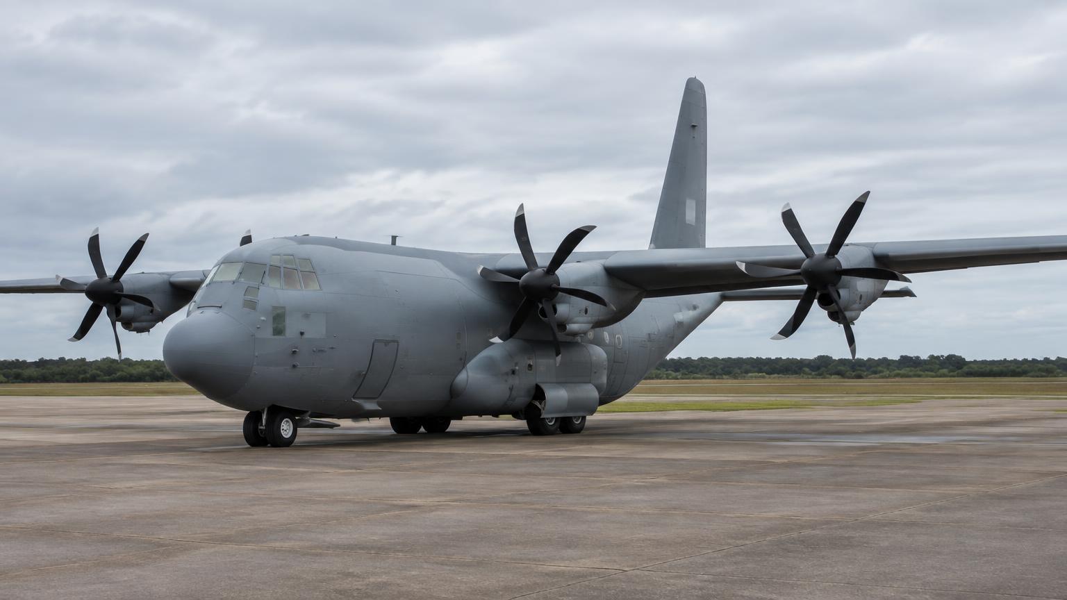
What it looks like
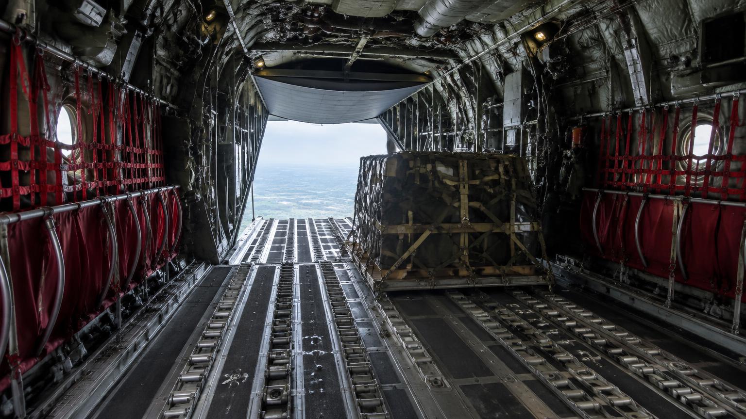
Technical data
| Item | Value |
|---|---|
| Max differential pressure | Approx. 15.3 inHg (7.5 psi) |
| Heat source | Engine or APU bleed air |
| Cooling | Dual air-cycle packs (L/R) |
| Zones | Flight station, cargo compartment, and underfloor |
| Max cabin altitude | Approx. 8,000 ft at 35,000 ft aircraft altitude |
Components
1.Air-cycle packs (2)
Located in sponsons; consist of heat exchangers and air-cycle machines to cool bleed air.
Located in the main landing gear sponsons, these units provide air conditioning for the entire aircraft.
- They use high-pressure engine bleed air that is cooled by ram air heat exchangers and expanded through a turbine to create cold air. The environmental control system manages the dual-pack operation to ensure cabin pressurization and thermal comfort during all phases of flight. Water separators and temperature control valves fine-tune the output before it enters the cabin distribution ducts.
| Air source | Engine bleed air |
| Max pressure | approx. 70 psi |
| Control | Digital ECS controller |
- Pack failure: Loss of cooling/pressurization, descend below 10,000 ft
- Controller fault: Manual pressure control required
- Check sponson air inlets for debris
- Verify outflow valve movement
- Test temperature control response
2.Outflow valve
Located in the forward fuselage; regulates cabin pressure by controlling the rate of air exhaust.
The outflow valve is situated in the forward fuselage and is the primary component for regulating cabin pressure.
- It modulates the exhaust rate of cabin air based on commands from the digital pressure controller to maintain a comfortable pressure schedule. The valve can be operated automatically by the mission computers or manually by the pilot during emergency conditions. Its precise movement prevents rapid pressure changes that could cause discomfort to the crew or structural damage.
| Air source | Engine bleed air |
| Max pressure | approx. 70 psi |
| Control | Digital ECS controller |
- Pack failure: Loss of cooling/pressurization, descend below 10,000 ft
- Controller fault: Manual pressure control required
- Check sponson air inlets for debris
- Verify outflow valve movement
- Test temperature control response
3.Safety valves
Provide overpressure and negative-pressure relief.
These pressure relief valves are mounted on the fuselage to provide a fail-safe backup for the cabin pressure system.
- They are calibrated to open automatically if the internal pressure exceeds 7.0 psi or falls below a negative limit of -0.5 psi. Since they are spring-loaded and purely mechanical, they function without electrical power or pilot intervention. This ensures the structural integrity of the C-130J even during a total electrical or controller failure.
| Air source | Engine bleed air |
| Max pressure | approx. 70 psi |
| Control | Digital ECS controller |
- Pack failure: Loss of cooling/pressurization, descend below 10,000 ft
- Controller fault: Manual pressure control required
- Check sponson air inlets for debris
- Verify outflow valve movement
- Test temperature control response
4.Temperature control valves
Modulate the mix of hot bleed air and cold pack air for each zone.
These valves are located within the air distribution manifold to regulate the temperature of specific aircraft zones.
- They mix hot bleed air with cold air from the packs to achieve the exact temperature selected by the flight crew on the ECS panel. The mission computers monitor zone sensors and adjust these butterfly valves continuously to maintain a stable environment. This allows for different temperature settings in the flight station compared to the cargo compartment.
| Air source | Engine bleed air |
| Max pressure | approx. 70 psi |
| Control | Digital ECS controller |
- Pack failure: Loss of cooling/pressurization, descend below 10,000 ft
- Controller fault: Manual pressure control required
- Check sponson air inlets for debris
- Verify outflow valve movement
- Test temperature control response
5.Underfloor heating fan/valves
Circulate warm air beneath the cargo floor for loadmaster and passenger comfort.
Located beneath the cargo compartment floor, this system provides radiant heat for personnel on long missions.
- Dedicated electric fans circulate warm air through a network of ducts to prevent cold spots at the floor level where troops or patients are located. The system is activated via a switch on the overhead panel and is thermostatically controlled to prevent overheating. It is especially useful during high-altitude transit or ground operations in arctic environments.
| Air source | Engine bleed air |
| Max pressure | approx. 70 psi |
| Control | Digital ECS controller |
- Pack failure: Loss of cooling/pressurization, descend below 10,000 ft
- Controller fault: Manual pressure control required
- Check sponson air inlets for debris
- Verify outflow valve movement
- Test temperature control response
6.Cabin pressure controller (digital)
Dual-channel controller that automatically schedules cabin altitude based on flight phase.
This dual-channel unit is located in the cockpit avionics rack and automates the aircraft pressurization schedule.
- It receives data from the mission computers regarding flight altitude and rate of climb to calculate the optimal outflow valve position. The controller features a built-in test capability and will automatically switch to the secondary channel if a fault is detected in the primary. This automation significantly reduces pilot workload compared to legacy C-130 models.
| Air source | Engine bleed air |
| Max pressure | approx. 70 psi |
| Control | Digital ECS controller |
- Pack failure: Loss of cooling/pressurization, descend below 10,000 ft
- Controller fault: Manual pressure control required
- Check sponson air inlets for debris
- Verify outflow valve movement
- Test temperature control response
Operation
- Bleed air is tapped from the engines and routed through the pack flow control valves to the air-cycle machines.
- The digital CNI-MU (Communication Navigation Identification Management Unit) or dedicated overhead panel allows the crew to set desired cabin altitude and rate of change.
- Temperature is managed via zone controllers that adjust trim air to maintain the selected temperature in the flight station and cargo hold independently.
- In 'Ditching' mode, the outflow valve is closed to prevent water ingress.
Controls
| Control | Function |
|---|---|
| Bleed air switches (1-4, APU) | Direct air to the manifold. |
| Pack switches (L/R) | Enable air-cycle cooling. |
| Zone temp selectors | Set desired temperature for Flight Station and Cargo. |
| Cabin altitude controller | Auto/Manual modes for pressurisation control. |
| Emergency depressurisation switch | Rapidly dumps cabin pressure. |
Indications
| Indication | Meaning |
|---|---|
| Cabin altitude/diff pressure on HDD | Display of current pressurisation status on the MFDs. |
| Zone temperature readouts | Real-time temperature for each compartment. |
| Pack / Bleed status | System synoptic page shows valve positions and temperatures. |
| CABIN ALTITUDE warning | Red warning if cabin altitude exceeds 10,000 ft. |
Failures & crew actions
| Failure | Effect / action |
|---|---|
| Pack failure | Loss of cooling/pressurisation from one side; remaining pack can maintain pressurisation with reduced capacity. |
| Outflow valve jam | May lead to overpressure or loss of pressurisation; use manual control or safety valves. |
| Bleed air leak | Detection loops trigger a warning; affected engine bleed must be isolated. |
| Loss of pressurisation | Emergency descent required; crew uses oxygen masks. |
Maintenance
- Pressure test of the fuselage to ensure seal integrity.
- Functional check of outflow and safety valves.
- Cleaning and inspection of pack heat exchangers.
- Filter replacement for recirculating air systems.
Deep dive · ATA 21
Air Conditioning and Pressurization
Bleed Air Supply
High-pressure bleed air is extracted from the 14th stage of the engine compressors or from the APU.
This air is used for cabin pressurization, air conditioning, and anti-icing.
| AC Packs | Dual Air Cycle Machines |
| Max Cabin Alt | approx. 8,000 ft at 35,000 ft |
| Differential Pressure | approx. 7.5 psi max |
Air Conditioning Packs
Two independent air cycle packs (Left and Right) cool the hot bleed air. The conditioned air is then distributed to the cockpit and cargo compartment.
The 'Underfloor' heating system provides additional warmth for the cargo hold during high-altitude flight.
Pressurization Control
Managed by a digital controller that regulates the outflow valves. It maintains a comfortable cabin altitude and rate of change during climb and descent.
Educational summary — verify against the official AMM/FCOM/POH for your aircraft.