Back to dashboard
Sections menu

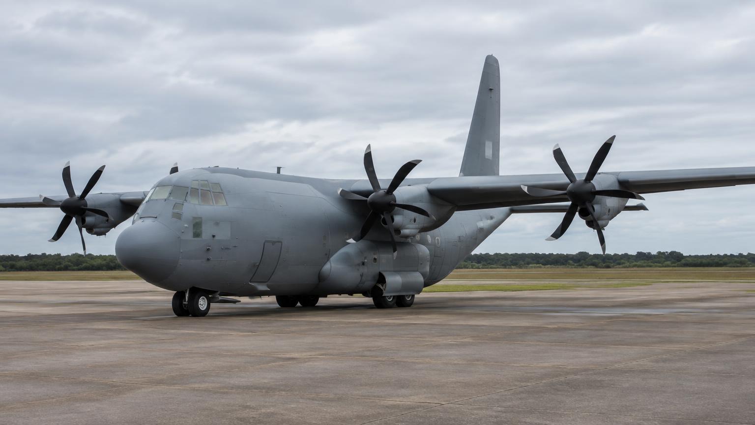
Lockheed Martin C-130J Super Hercules · Interactive FCOM

Full manual

Organised like the official Flight Crew Operating Manual with maintenance by ATA chapter. Search across every section.

Unverified — check your manualText on this page is written from general knowledge. Figures marked ✓ are checked against official FAA/EASA data.See verified data
1

General

Engines4 x Rolls-Royce AE 2100D3 turboprops, approx. 4,590 shp each, FADEC
Propellers6-blade Dowty R391 composite scimitar, reversible pitch
MTOWapprox. 155,000 lb normal (175,000 lb max overload)
Crew2 pilots + loadmaster (no flight engineer/navigator on the J)
Cockpit4 colour MFDs, 2 HUDs, dual mission computers
Landing gearRetractable tricycle, tandem mains into fuselage sponsons

Model applicability

  • C-130J Super Hercules (baseline) — 1999 - present · S/N By line number / operator - see Flight Manual applicability
  • C-130J-30 (stretched) — 1999 - present · S/N By line number - see Flight Manual applicability
  • C-130A - H (legacy Hercules) — 1956 - 1996 (production) · S/N By block number - see legacy flight manuals
  • KC-130J (tanker) — 2004 - present · S/N By line number / operator
  • LM-100J (civil freighter) — 2017 - present · S/N By MSN - civil type certificate
2

Limitations

Speeds (KIAS)

Max operating speed (VMO), typicalapprox. 345 kt / varies by weight
Max flap extended speedapprox. 150-180 kt depending on flap setting
Max gear extended/operating speedapprox. 180-200 kt
Max demonstrated crosswindapprox. 25-30 kt

Powerplant

Engine4 x Rolls-Royce AE 2100D3, approx. 4,590 shp each
PropellerDowty R391, 6-blade, reversible pitch
Torque/ITT limitsPer FADEC schedule, see Flight Manual

Weight & envelope

MTOW normalapprox. 155,000 lb
MTOW max overloadapprox. 175,000 lb
Internal fuelapprox. 45,900 lb
Cargo holdPressurised
3

Abnormal & Emergency Procedures

Engine Fire / Failure In Flight

Affected power leverRETARD/CONFIRM
Condition lever (affected engine)FUEL OFF / FEATHER
Fire handle (affected engine)PULL, DISCHARGE AS REQUIRED
Remaining enginesMONITOR, ADJUST POWER
Crew/loadmasterNOTIFY, SECURE CARGO

Flight Manual memory items for engine fire/failure; exact sequence per TO 1C-130J-1.

Rejected Takeoff

Power leversRETARD TO IDLE/GROUND IDLE
PropellersREVERSE AS REQUIRED
BrakesMAXIMUM AS REQUIRED
Flight controlsMAINTAIN DIRECTIONAL CONTROL

Cabin Depressurization

Oxygen masks (crew & loadmaster)ON, 100%
Pressurization controllerCHECK / MANUAL
Emergency descentINITIATE AS REQUIRED
Cargo compartmentCHECK SECURE, NOTIFY LOADMASTER

Aerial Delivery / Ramp Malfunction

Ramp/door positionVERIFY (per CAS/indicator)
LoadmasterCOORDINATE, HALT DROP IF UNSAFE
Airspeed & configurationWITHIN AIRDROP LIMITS
Emergency ramp/door controlUSE IF NORMAL SYSTEM FAILS

Coordinate closely with the loadmaster; airdrop and paratroop procedures are crew-coordination intensive.

4

Normal Procedures

Expanded, step-by-step versions with explanations: open the interactive procedures →

Preflight Walkaround (amplified)

  1. 1. General condition — WALK AROUND, nose to tail, both sides, including the ramp
    A loadmaster or pilot walkaround catches skin damage, leaks, missing fasteners and unlatched panels before they become inflight problems on a four-engine airlifter.
  2. 2. Propellers (6-blade Dowty R391) — CHECK blades, spinner, de-ice boots, no leaks at the hub
    The composite scimitar propellers are reversible-pitch — nicks or de-ice boot damage affect both forward thrust and reverse-pitch braking on landing.
  3. 3. Engines (AE 2100D3) & FADEC — CHECK cowlings secure, inlets clear, no fuel/oil leaks
    Each turboprop has its own FADEC channel; a blocked inlet or loose cowl panel is only caught by a close visual check.
  4. 4. Main gear sponsons & tandem bogies — CHECK tyres, struts, no hydraulic leaks
    The tandem main gear retracts into fuselage sponsons rather than the wing — inspect both forward and aft bogies on each side.
  5. 5. Flaps, ailerons, rudder, elevator — CHECK surfaces free and undamaged
    The Fowler flaps and all flight control surfaces must move freely and show no skin damage before flight.
  6. 6. APU inlet/exhaust (left sponson area) — CHECK clear and undamaged
    The gas-turbine APU supplies electrical power and bleed air for engine start — a blocked inlet prevents a normal APU start.
  7. 7. Cargo ramp, door and paratroop doors — CHECK secure, seals intact, locking pins stowed as required
    The rear ramp and door are used for cargo, troops and airdrop — door seals also affect cabin pressurisation.
  8. 8. Fuel tanks & sumps — CHECK quantity, drain sumps for water/contamination
    Four integral wing tanks plus two auxiliary tanks (and optional external pylon tanks) feed the engines; approx. 45,900 lb internal fuel on the J model.
  9. 9. Pitot/static ports, AoA probes — CHECK clear and undamaged
    Feeds the air data computers for the glass cockpit MFDs and HUDs — a blocked port gives unreliable airspeed.

Cockpit Preparation (amplified)

  1. 1. BATTERY switch — ON
    Powers the essential DC bus so the mission computers and displays can initialise before the engines or APU run.
  2. 2. 4 MFDs — CHECK self-test, select ENGINE/SYSTEM pages
    Confirms all four displays and the dual mission computers are alive; any display can be reconfigured to show engine, system or navigation data.
  3. 3. HUD combiners — STOW/ADJUST, CHECK self-test
    Both pilots use a HUD for low-level, airdrop and night formation flying — verify symbology and brightness before flight.
  4. 4. CNI-MU — CHECK database, enter route if known
    The Communication/Navigation/Identification Management Unit loads nav data the FMS and autopilot will use for route guidance.
  5. 5. Generator panel — CHECK OFF for start (engine/APU driven) or EXT PWR connected
    Each of the four engines drives its own generator plus the APU generator for 28 VDC and 115 VAC 400 Hz power.
  6. 6. Fuel panel — CHECK tank boost pumps and crossfeed OFF/normal
    Verifies normal feed configuration before engine start — crossfeed is only used for fuel management or an engine-out condition.
  7. 7. Trim panel — CHECK pitch/roll/yaw trim SET to takeoff position
    A large four-engine aircraft needs correct trim set before engine start checks and taxi.
  8. 8. Autopilot panel — CHECK OFF, self-test as applicable
    Confirms the autopilot/flight director is ready but not engaged until airborne.
  9. 9. Parking brake — SET
    Holds the aircraft stationary through the engine and APU start sequence.

Engine Start — APU and 4 Engines (FADEC) (amplified)

  1. 1. Area around aircraft — CLEAR, propeller arcs clear on all four engines
    Standard caution for a turboprop with reversible-pitch propellers — nobody near any of the four prop discs.
  2. 2. APU CONTROL PANEL — START
    The gas-turbine APU in the left sponson area supplies 28 VDC/115 VAC power and bleed air for engine start without external power.
  3. 3. APU parameters — MONITOR EGT, RPM to AVAIL
    Confirms the APU is stable before drawing on it for an engine start.
  4. 4. APU generator — ON, CHECK ON LINE
    Powers the aircraft electrical buses from the APU before any engine is running.
  5. 5. Condition Lever 3 (inboard, right) — GROUND IDLE
    Commands FADEC to begin the automatic start sequence on the first engine; engine 3 is often started first as it also drives key hydraulics.
  6. 6. Start sequence (NG, TIT, NF) — MONITOR
    The dual-channel FADEC runs the start automatically — starter motoring, fuel and ignition scheduled by NG — but the crew still watches for a hot or hung start.
  7. 7. Remaining Condition Levers (4, 2, 1) — GROUND IDLE in turn
    Repeats the automatic FADEC start sequence on each remaining engine until all four are running and stable at ground idle.
  8. 8. All four engines at ground idle — CHECK NG, NF, TIT, torque stable
    Confirms all four Rolls-Royce turboprops are healthy before taxi.
  9. 9. Engine generators 1-4 — ON, CHECK charging
    Each engine-driven generator now supplies the aircraft electrical system; the APU generator can be taken off line.
  10. 10. APU — OFF (once engine generators are on line)
    No longer needed once engine-driven electrical and bleed air are available.

Taxi (amplified)

  1. 1. Parking brake — RELEASE
    Frees the aircraft to taxi once engine checks and ATC clearance are complete.
  2. 2. Power levers — ADVANCE slightly to start rolling, then retard
    The AE 2100D3 engines with their large six-blade props produce strong thrust even near idle — small movements are enough to taxi.
  3. 3. Rudder pedals / nosewheel steering — STEER via tiller or differential braking/power
    The C-130J's nosewheel steering (via rudder pedals/tiller) and differential power let the crew manage a wide turning radius on narrow taxiways.
  4. 4. Brakes — TEST — smooth, even response
    Confirms the brakes will provide reliable stopping power before committing to the runway, especially on wet or unimproved surfaces.
  5. 5. Flight controls — FREE & CORRECT (checked before or during taxi)
    Confirms ailerons, elevator and rudder move the right way with hydraulic boost before takeoff.
  6. 6. Engine & system pages — MONITOR temperatures, pressures, no new cautions
    A four-engine, high-gross-weight aircraft benefits from a continuous instrument scan while taxiing to the runway.
  7. 7. Flaps — SET for takeoff per performance data
    The Fowler flaps are normally set before taxi or during the before-takeoff checks, depending on operator SOP.

Normal Takeoff (amplified)

  1. 1. Brakes — HOLD, then RELEASE as power is set
    Lets all four engines stabilise symmetrically before the takeoff roll begins.
  2. 2. Power levers — ADVANCE to takeoff power, all four together
    Symmetrical power application keeps the aircraft tracking straight down the runway; FADEC trims small differences automatically.
  3. 3. Engine torque / TIT / NP — CHECK set and matched across all four engines
    Confirms takeoff power is correctly set and no single engine is lagging before committing to the takeoff.
  4. 4. Rudder — TRIM/STEER to track runway centreline
    Asymmetric thrust effects and crosswind both require active rudder input during the roll.
  5. 5. HUD / airspeed tape — CALL V1, VR
    Both pilots cross-check the HUD and panel airspeed for the critical takeoff speed callouts.
  6. 6. Rotation — SMOOTH to the takeoff attitude at VR
    A gentle, positive rotation lifts the high wing off without over-rotating the long fuselage of the J-30 variant.
  7. 7. Landing gear — UP on positive rate of climb
    Reduces drag once a climb is confirmed on the altimeter/VSI.
  8. 8. Flaps — RETRACT on schedule as speed increases
    Flap retraction follows the published schedule to avoid a sink or a flap overspeed.
  9. 9. Flight director / autopilot — ENGAGE once established in the climb
    Reduces crew workload once past the critical low-energy phase of the takeoff.

Climb (amplified)

  1. 1. Power levers — SET climb power per performance chart
    Climb power is normally below maximum continuous to manage TIT and fuel flow over a long climb.
  2. 2. Engine parameters — MONITOR torque, TIT, NP balanced across all four
    An unbalanced engine in the climb is easier to catch early than after levelling at cruise.
  3. 3. Autopilot vertical mode — SELECT climb speed or vertical speed mode
    Couples the AFCS to hold a target airspeed or rate of climb, freeing the crew to manage systems and navigation.
  4. 4. Trim — ADJUST as speed and configuration change
    Keeps control forces light as the aircraft accelerates and climbs.
  5. 5. Cabin pressurisation — MONITOR cabin altitude and rate
    The pressurised cargo hold must be scheduled to arrive near destination/cruise cabin altitude without excessive climb rate.
  6. 6. Fuel page — MONITOR fuel used vs plan, tank balance
    Confirms fuel burn matches the flight plan and the four tanks remain balanced.

Cruise (amplified)

  1. 1. Power levers — SET cruise power per performance chart
    Cruise power split evenly across all four engines gives the planned cruise speed and fuel burn.
  2. 2. Autopilot modes — ALT / HDG / NAV as required
    Couples the autopilot to altitude, heading or the CNI-MU route to reduce crew workload en route.
  3. 3. Trim — SET for hands-off level flight
    Reduces control forces and fatigue on long transport legs.
  4. 4. Engine & system pages — MONITOR NG, TIT, torque, hydraulics, fuel
    Displays rotate to show the parameter needing attention, but a periodic scan catches slow trends across four engines.
  5. 5. Fuel boost pumps / crossfeed — CHECK, balance tanks if required
    Keeps all four engines fed evenly from the wing, auxiliary and optional external tanks and keeps CG within limits.
  6. 6. CNI-MU route progress — MONITOR next waypoint, ETA, fuel at destination
    Confirms the flight plan built on the CNI-MU/FMS is tracking as expected.
  7. 7. Loadmaster / cargo hold — CHECK cargo security and cabin conditions periodically
    On a transport mission the loadmaster monitors the load and cabin systems throughout the cruise.

Descent (amplified)

  1. 1. CNI-MU / FMS — REVIEW arrival, approach and descent profile
    Confirms the correct STAR/approach is loaded before starting down.
  2. 2. Autopilot altitude — SET new cleared altitude, SELECT descent mode
    Couples the AFCS to fly the descent profile accurately.
  3. 3. Power levers — RETARD to descent power
    Reduces power smoothly across all four engines for a controlled descent rate.
  4. 4. Cabin pressurisation — SCHEDULE rate for landing field elevation
    The cargo hold must be unpressurised (or near ambient) by touchdown without an uncomfortable or unsafe cabin rate of change.
  5. 5. Engine & system pages — MONITOR during power reduction
    Confirms symmetric power reduction and no abnormal indications as workload increases.
  6. 6. HUD / approach briefing — BRIEF minimums, missed approach, terrain
    Both pilots cross-check the approach plan before starting the final descent segment.

Instrument Approach (amplified)

  1. 1. Autopilot approach mode — ARM localiser/glideslope or GPS approach
    Couples the AFCS to the final approach course and vertical path.
  2. 2. Flaps — EXTEND in stages per speed schedule
    Fowler flaps are extended progressively to slow the aircraft while maintaining lift.
  3. 3. Landing gear — DOWN, CHECK three green
    Tandem main gear and nose gear must show down and locked before landing.
  4. 4. Power levers — ADJUST to maintain approach speed
    Small power corrections hold the stabilised approach speed on the glidepath.
  5. 5. HUD flight path symbology — FLY the velocity vector onto the runway aim point
    The HUD lets the pilot keep eyes outside while flying a precise glidepath, especially useful at night or in marginal weather.
  6. 6. Approach / engine page — FINAL CHECK — stabilised by gate altitude
    On speed, on path, configured and engines matched — otherwise go around.
  7. 7. Pedals — TRIM for crosswind, align with runway
    A crosswind requires continuous rudder/pedal input through the approach.

Normal Landing with Reverse Pitch (amplified)

  1. 1. Flare — SMOOTH, reduce rate of descent at the threshold
    The high wing and tandem main gear tolerate a firm touchdown, but a smooth flare reduces structural loads and improves control.
  2. 2. Power levers — RETARD to flight idle at touchdown
    Removes power before weight comes fully onto the main gear.
  3. 3. Nosewheel — LOWER gently after main gear touchdown
    Keeps weight progressively onto all gear before using nosewheel steering.
  4. 4. Power levers — SELECT GROUND/REVERSE RANGE (below the flight idle gate)
    The Dowty R391 propellers are reversible-pitch — unlike a jet, the C-130J has no separate thrust reversers; the propeller blades themselves reverse pitch to produce reverse thrust.
  5. 5. Condition levers — CONFIRM ground range/max RPM as required for reverse
    Propeller RPM must be in the correct range for FADEC to command reverse blade angle safely.
  6. 6. Wheel brakes — APPLY smoothly in conjunction with reverse pitch
    Reverse pitch plus wheel brakes together give short-field stopping performance without overheating the brakes alone.
  7. 7. Rudder/nosewheel steering — MAINTAIN centreline through reverse pitch
    Reverse pitch at higher power can induce a yawing tendency, especially with any asymmetry between engines — active steering keeps the aircraft straight.
  8. 8. Power levers — OUT OF REVERSE by taxi speed
    Avoids FOD ingestion and unnecessary wear once the aircraft has slowed to a safe taxi speed.

Go-Around / Missed Approach (amplified)

  1. 1. Power levers — ADVANCE to go-around power, all four together
    Maximum available power is needed immediately to stop the descent and begin a climb.
  2. 2. Pitch — ROTATE to the go-around attitude
    Establishes a positive climb while the engines spool up to go-around power.
  3. 3. Landing gear — UP on positive rate of climb
    Reduces drag once the climb is confirmed.
  4. 4. Flaps — RETRACT on schedule
    Removes drag in stages to avoid a sink during retraction.
  5. 5. Rudder — TRIM for the power and configuration change
    A sudden increase to go-around power changes the trim and pedal forces needed.
  6. 6. Autopilot / flight director — FOLLOW missed approach guidance, ENGAGE when stable
    Reduces workload once a positive climb and clean configuration are established.

Assault / Short-Field Landing (amplified)

  1. 1. HUD / approach briefing — BRIEF short-field distances, obstacles, and go-around criteria
    Assault strips are short and often unimproved — the crew must know the usable landing distance and abort point before committing.
  2. 2. Flaps — FULL for maximum lift at minimum speed
    Maximises lift to allow the slowest safe approach speed, shortening the landing roll.
  3. 3. Power levers — STEEP, POWER-ON approach to a near-idle flare
    A steeper approach angle and controlled power clear obstacles close to the threshold without floating down the strip.
  4. 4. Touchdown — FIRM, positive touchdown at the planned aim point
    A firm touchdown close to the threshold is deliberate on an assault landing — floating wastes precious stopping distance.
  5. 5. Power levers — MAXIMUM REVERSE PITCH immediately at touchdown
    Immediate reverse pitch on all four propellers gives aerodynamic braking from the first moment of ground contact.
  6. 6. Wheel brakes — MAXIMUM, firm and sustained
    Combined with reverse pitch, maximum braking achieves the shortest possible ground roll on a tactical strip.
  7. 7. Rudder/nosewheel steering — ACTIVE control through heavy reverse and braking
    High reverse power and hard braking both increase the tendency to swerve — continuous correction is needed to stay on a narrow strip.
  8. 8. Loadmaster / cargo — CONFIRM cargo and load secure for rapid ground operations
    Assault landings are often followed immediately by an engine-running offload — the load must be ready and secure.

Airdrop / Ramp Operation (amplified)

  1. 1. Ramp & cargo door — OPEN per checklist, CHECK rigging and restraints
    The rear ramp and door must be fully open and locked before any cargo or personnel drop, with all rigging inspected by the loadmaster.
  2. 2. Loadmaster — CONFIRM load ready, static lines/extraction system rigged
    The loadmaster runs the cargo compartment and gives the final go/no-go for the drop independently of the flight deck.
  3. 3. Flaps — SET airdrop configuration per chart
    A specific flap setting gives the stable, slow airdrop speed needed for a safe cargo or personnel exit.
  4. 4. Power levers — SET airdrop speed and hold steady
    A constant, stabilised airspeed and altitude on the drop run keeps the load's trajectory predictable for accurate delivery.
  5. 5. CNI-MU / navigation — FLY to the computed air release point (CARP)
    The CARP accounts for wind, altitude and load type so the cargo or troops land on the intended drop zone.
  6. 6. Autopilot/flight director — HOLD heading and altitude precisely through the drop run
    Even small deviations during the drop run can move the impact point significantly, especially for a Container Delivery System (CDS) drop.
  7. 7. Loadmaster signal / green light — RELEASE cargo or jump command at the CARP
    Release is coordinated between the flight deck and the loadmaster so timing and the aircraft's position line up.
  8. 8. Pitch/trim — COMPENSATE for the sudden aft CG shift as the load leaves
    A heavy load leaving the ramp suddenly moves the CG forward and can pitch the nose down — anticipate and correct.
  9. 9. Ramp & cargo door — CLOSE once clear and checklist complete
    Restores normal aerodynamic configuration and cabin integrity after the drop.

Engine Fire (In Flight) (amplified)

  1. 1. ENG FIRE warning — CONFIRM which engine, cross-check TIT/other parameters
    Acting on the wrong engine turns a single-engine fire into a far more serious multi-engine emergency.
  2. 2. Affected Power Lever — RETARD to flight idle
    Reduces fuel flow and heat to the affected engine before shutting it down.
  3. 3. Affected Condition Lever — FUEL OFF / STOP
    Shuts off fuel to the affected engine and commands the propeller toward feather.
  4. 4. Engine fire handle (affected engine) — PULL
    Isolates the engine's fuel, hydraulic and electrical connections and arms the extinguisher bottle.
  5. 5. Fire extinguisher — DISCHARGE
    Delivers the agent to the engine nacelle to put the fire out.
  6. 6. Fire warning / engine parameters — MONITOR fire warning clears
    Confirms the fire is out; if it persists, the second bottle is discharged per checklist.
  7. 7. Rudder trim — TRIM for asymmetric thrust with one engine out
    Losing one of four engines still creates a yawing moment that must be trimmed out.
  8. 8. Nearest suitable airfield — PLAN diversion
    An engine fire, even if extinguished, is always followed by a precautionary or emergency landing.

Engine Failure & Propeller Feathering (amplified)

  1. 1. Engine parameters — IDENTIFY the failed engine — torque/NG/TIT drop
    Correct identification is critical before any lever is moved on a four-engine aircraft.
  2. 2. Affected Power Lever — RETARD to flight idle
    Removes commanded power from the failed engine while the crew confirms the failure.
  3. 3. Affected Condition Lever — FEATHER
    Commands the Dowty propeller to feather, streamlining the blades to stop windmilling drag and possible further damage.
  4. 4. NP / torque (failed engine) — CONFIRM feathered, NP at zero
    A windmilling, unfeathered propeller creates severe drag and asymmetric handling difficulty.
  5. 5. Rudder — TRIM to counter asymmetric thrust and drag
    Losing one engine of four creates a yaw/roll toward the dead engine that must be trimmed and held.
  6. 6. Remaining three power levers — ADJUST power as required to maintain altitude/climb
    The remaining three engines, each FADEC-controlled, can typically maintain controlled flight and often a climb depending on weight and altitude.
  7. 7. Remaining engines — MONITOR for any additional abnormal indications
    A common-cause failure (e.g. fuel contamination) could threaten more than one engine — stay alert to the others.
  8. 8. Nearest suitable airfield — PLAN diversion and approach
    Performance with one engine feathered must be checked against the diversion field's elevation and length.

Route Entry on CNI-MU (amplified)

  1. 1. CNI-MU keypad — SELECT FLIGHT PLAN / ROUTE function
    Opens the active flight plan page shared with the mission computers and displayed on the MFDs.
  2. 2. Departure point — ENTER ident or coordinates, VALIDATE
    First leg of the route — can be an airfield or a lat/long for tactical or austere strips with no published identifier.
  3. 3. Waypoints / airways — ENTER each fix in sequence, VALIDATE
    Builds the route leg by leg; the CNI-MU supports named waypoints, airways and raw coordinates for low-level or tactical routing.
  4. 4. Destination / drop zone — ENTER ident or coordinates, VALIDATE
    Closes the route for distance, fuel and ETA calculations, and may be a computed air release point for an airdrop mission.
  5. 5. Route on the map page — CHECK track, distance and sequence
    A visual check against the planned route catches a mistyped waypoint or a wrong fix sharing a similar identifier.
  6. 6. NAV mode — ARM/SELECT to couple the autopilot to the route
    Lets the autopilot fly the entered flight plan laterally once airborne.
  7. 7. Fuel/performance predictions — CROSS-CHECK against the flight plan
    Confirms the entered route matches the planned fuel and time, catching gross entry errors early.

Autopilot / Flight Director (AFCS) (amplified)

  1. 1. Flight director — ON, select initial mode
    Provides pitch and roll guidance cues on the HUD and MFDs before the autopilot itself is engaged.
  2. 2. AP ENGAGE — PRESS (aircraft trimmed, above minimum engagement altitude)
    Engaging in trimmed flight avoids a jolt as the autopilot takes over pitch and roll.
  3. 3. HDG mode — SELECT with heading bug set
    Couples the autopilot to fly a selected heading rather than the CNI-MU route.
  4. 4. NAV mode — SELECT (requires an active CNI-MU route)
    Couples the autopilot to follow the lateral flight plan entered on the CNI-MU.
  5. 5. ALT / VS mode — SELECT vertical mode
    ALT holds a selected altitude; VS holds a selected rate of climb or descent.
  6. 6. Altitude preselect — SET target altitude
    The autopilot captures and levels at the selected altitude automatically.
  7. 7. Approach mode — ARM then couple on final
    Couples localiser/glideslope or GPS approach guidance; the crew monitors and takes over for landing.
  8. 8. AP DISCONNECT button — PRESS to disconnect
    Always know the quick disconnect on the yoke — immediate return to manual control.

After Landing & Taxi-In (amplified)

  1. 1. Power levers — GROUND IDLE (out of reverse)
    Returns to normal ground idle once the aircraft has slowed to a safe taxi speed.
  2. 2. Flaps — RETRACT per checklist
    Configures the aircraft for taxi and protects the flaps from ground debris or FOD.
  3. 3. Engine & system pages — CHECK no new cautions from the flight
    A final scan before deciding to shut down, reposition, or prepare for an engine-running offload.
  4. 4. Nosewheel steering — STEER to parking or offload position
    Taxi to the ramp or offload point as directed by ground control or the loadmaster for cargo operations.
  5. 5. Loadmaster / cargo hold — PREPARE for offload or onward taxi as mission requires
    Many C-130 missions continue directly into an engine-running onload/offload rather than a full shutdown.

Engine Shutdown (amplified)

  1. 1. Parking brake — SET
    Holds the aircraft stationary through the shutdown sequence.
  2. 2. APU — START (if needed for power during shutdown)
    Provides uninterrupted electrical power while the engines are shut down.
  3. 3. Power levers — GROUND IDLE, allow a cooling period
    A short idle period cools the turbines before fuel is cut, protecting the hot section of each AE 2100D3.
  4. 4. Condition Levers 1-4 — FUEL OFF / STOP, in sequence
    Shuts off fuel to each engine via its FADEC; NG and NP decay to zero.
  5. 5. All engines — MONITOR NG/NP decay to zero
    Confirms every engine has fully spooled down before anyone approaches the propellers.
  6. 6. Engine generators — OFF as each engine shuts down
    No longer driven once the corresponding engine stops.
  7. 7. APU — OFF (once no longer needed)
    Final power source shutdown once the aircraft is secured or external power is connected.
  8. 8. BATTERY switch — OFF
    Prevents battery drain while the aircraft is parked.

Exterior Inspection — Nose & Flight Deck Area

Pitot/static ports, AOA vanesCLEAR, NO DAMAGE
Nose landing gear, tyres, doorsCHECK, NO LEAKS
Windscreens & HUD combinersCONDITION, CLEAN
RadomeCONDITION

Wings, Engines & Propellers

Engine nacelles, cowlingsSECURE, NO LEAKS
Propeller blades, spinnersCONDITION, NO FOD/CRACKS
Wing leading edges, flapsCONDITION
Main gear, sponsons, tyres, brakesCHECK
Fuel vents & capsSECURE

Fuselage, Ramp & Tail

Ramp & cargo door, sealsCONDITION, OPERATE CHECK
Paratroop doorsSECURE, OPERATE CHECK
APU inlet/exhaust (sponson area)CLEAR
Empennage, elevator, rudderCONDITION
Static dischargers, antennasCONDITION

Flight Deck Preflight

Battery/external powerCHECK
Mission computers & MFDsSELF-TEST COMPLETE
HUDsALIGN & TEST
FMS/CNI-MUROUTE LOADED
Fuel quantity & crossfeedCHECK
Hydraulic panels (utility/booster/aux)CHECK

Before Start

Loadmaster/cargo compartmentSECURE, READY
Parking brakeSET
APUSTART, ON LINE
Fuel quantity & crossfeedSET AS REQUIRED
Flight controlsFREE & CORRECT
Mission computers, FMSCHECKED

Engine Start & Taxi

Engine start sequence (3-2-1-4 or per checklist)INITIATE, MONITOR FADEC
PropellersOUT OF FEATHER, CHECK
GeneratorsON LINE, CHECK LOAD
FlapsSET FOR TAXI/TAKEOFF
Taxi/takeoff briefingCOMPLETE

Takeoff & Landing

Power leversSET TAKEOFF POWER, FADEC MONITORED
V1/VR/V2 (or tactical equivalents)CALL
Positive rateGEAR UP
Landing: GearDOWN, 3 GREEN
FlapsLANDING SETTING
Propellers (after touchdown)REVERSE AS REQUIRED
5

Performance

How performance is worked out

C-130J crews plan takeoff, climb, cruise and landing using the flight manual performance data and the mission computers' integrated performance functions. Inputs include gross weight, centre of gravity, runway length and surface, slope, wind, temperature, pressure altitude and obstacles. The system returns refusal speed, rotation and takeoff speeds, minimum control speeds and stopping distances.

Typical figures (C-130J / C-130J-30)

Representative values only - never use for planning.

Max normal takeoff weightapprox. 155,000 lb (70,300 kg)
Max overload takeoff weightapprox. 175,000 lb (79,400 kg)
Max payloadapprox. 42,000-44,000 lb
Max cruise speedapprox. 355-360 KTAS
Service ceilingapprox. 28,000 ft (unpressurised ops lower)
Takeoff distance (155,000 lb, SL ISA)approx. 3,100 ft ground roll
Landing ground roll (assault, lighter weight)approx. 1,500-2,000 ft
Range with 35,000 lb payloadapprox. 1,800-2,000 nm
Ferry rangeapprox. 2,800+ nm

Four-engine turboprop characteristics

Each AE 2100D3 drives a six-blade R391 propeller through a reduction gearbox. Thrust is set by the FADEC and propeller control, giving immediate power response compared with a jet. Because the props blow over most of the wing, extra lift at high power lowers stall speed and gives the C-130 its short-field ability.

Engine-out performance

Takeoff speeds must stay above air minimum control speed (VMCA) for the loss of an outboard engine, which is the critical case. At heavy weights the refusal speed and continued-takeoff distance limit the runway needed. With one engine out the aircraft can climb at most weights; with two out on one side performance is severely limited.

Short and unprepared fields

Assault takeoffs use max effort technique: high power against the brakes, early rotation and a steep climb-out. Assault landings use a steep approach, firm touchdown on a marked point and immediate ground-idle and reverse pitch, plus heavy braking. Semi-prepared runways (gravel, dirt) increase rolling resistance on takeoff and reduce braking effectiveness on landing, so distances are corrected for runway condition reading (RCR).

Reverse pitch and stopping

The C-130 has no thrust reversers. Pulling the throttles behind ground idle moves the propeller blades into reverse pitch, giving strong deceleration and allowing the aircraft to back up on the ground. Brakes with antiskid share the load; on wet or icy surfaces reverse provides most of the stopping.

Cruise and range

Range depends heavily on payload and fuel. Internal fuel is about 45,900 lb in four integral wing tanks plus two auxiliary tanks; external pylon tanks extend ferry range. Typical long-range cruise sits around FL220-280; airdrop runs are flown low and slow (approx. 130-150 KIAS).

Airdrop and tactical considerations

Ramp-open flight, troop jumps and heavy-equipment drops change drag and centre of gravity sharply. The loadmaster and pilots compute CG shift for each extraction, and the aircraft is trimmed and flown at a fixed airdrop speed and altitude.

Typical figures for study only. Real performance comes from the approved flight manual and performance tools.

7

Airplane & Systems Description

Glass Cockpit, HUDs & Mission Computers ATA 22, 23, 31, 34, 76, 77

Where it is

Location of Glass Cockpit, HUDs & Mission Computers
Glass Cockpit, HUDs & Mission Computers

What it looks like

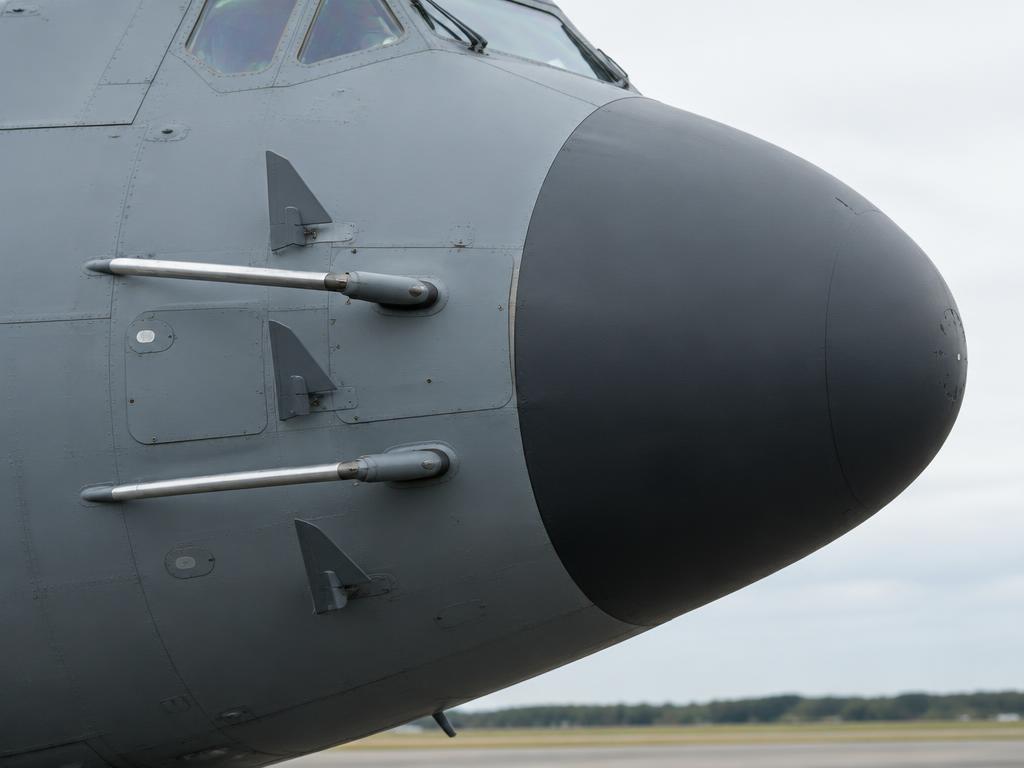
Nose radome, pitot probes and AOA vanes
Nose radome, pitot probes and AOA vanes · illustrative image

A two-pilot glass cockpit with four colour multifunction displays, dual head-up displays (HUDs) and dual mission computers replaces the flight engineer and navigator stations of earlier Hercules models.

  • Four interchangeable colour MFDs present primary flight, navigation, engine and systems data; any display can take over another's data if one fails.
  • Dual HUDs project flight path, airspeed, altitude and approach guidance onto the windscreen so pilots can fly heads-up, which matters for low-level tactical flying, airdrop runs and poor-visibility approaches to unprepared strips.
  • Dual mission computers run the FMS/CNI-MU (Communication, Navigation, Identification Management Unit), integrating navigation, radios and identification systems and driving the keypads on the centre console.
  • An integrated autopilot and autothrottle hold speed, altitude and flight path, including coupled approaches, reducing crew workload on a two-pilot flight deck that no longer carries a flight engineer or navigator.
  • Because the aircraft has no flight engineer, engine and systems synoptic pages on the MFDs are designed so either pilot can monitor all four engines and aircraft systems directly.

Rolls-Royce AE 2100D3 Turboprops ATA 61, 71, 72, 73, 74, 76, 77, 79, 80

Where it is

Location of Rolls-Royce AE 2100D3 Turboprops
Rolls-Royce AE 2100D3 Turboprops

What it looks like

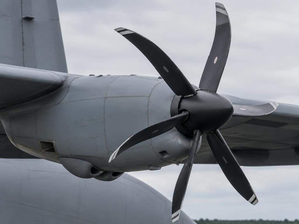
AE 2100D3 turboprop nacelle with six-blade R391 propeller
AE 2100D3 turboprop nacelle with six-blade R391 propeller · illustrative image

Four FADEC-controlled AE 2100D3 turboprops, each approx. 4,590 shp, drive 6-blade Dowty R391 composite scimitar propellers with reversible pitch and no separate thrust reversers.

  • Each engine has its own full-authority digital engine control (FADEC) that schedules fuel flow and coordinates propeller blade angle automatically, replacing the manual power/prop lever coordination of earlier Hercules models.
  • The AE 2100D3 is a free-turbine turboprop: a gas generator section drives a separate power turbine, which drives the propeller gearbox through a reduction gearbox.
  • The Dowty R391 propeller is a 6-blade composite scimitar design with reversible pitch; selecting reverse pitch (not a separate thrust reverser) rotates the blades to a negative angle, redirecting thrust forward for a short landing roll or backing up on the ramp.
  • Because there is no thrust reverser duct, reverse thrust comes entirely from reversing propeller blade angle while the engine keeps running, which is why prop condition levers and power levers are coordinated carefully during ground operations.
  • An auto-feather/auto-coarsen system can automatically move a failing engine's propeller to reduce drag, important with an asymmetric four-engine failure during takeoff.

High Wing, Fowler Flaps & Flight Controls ATA 27, 28, 57

Where it is

Location of High Wing, Fowler Flaps & Flight Controls
High Wing, Fowler Flaps & Flight Controls

What it looks like

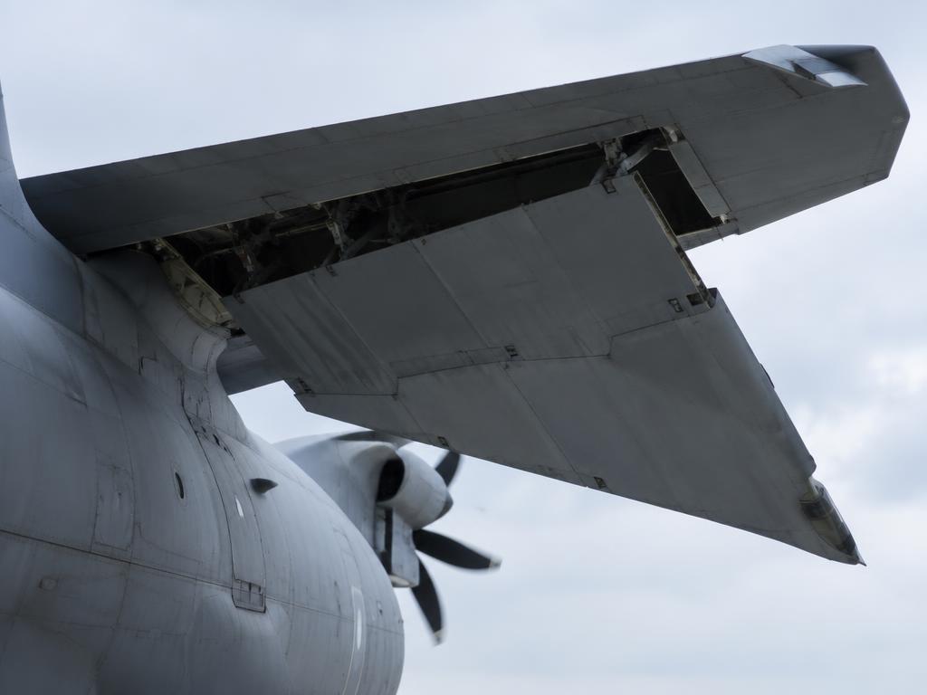
High wing trailing edge with Fowler flap extended
High wing trailing edge with Fowler flap extended · illustrative image

A high-mounted wing carrying four engines and large Fowler flaps gives short-field lift and keeps propellers and intakes clear of rough, unprepared runways.

  • The high-wing layout keeps the propellers and engine intakes well above dirt, gravel or snow strips, and leaves the fuselage low to the ground for drive-on cargo loading.
  • Large Fowler flaps extend aft and down to increase wing area and camber, giving the low approach speeds needed for short, unprepared landing zones.
  • Primary flight controls (ailerons, elevator, rudder) are hydraulically powered with manual reversion available, giving pilots direct feel and backup if hydraulic power is lost.
  • Spoilers/lift-dump and roll-control surfaces work with the ailerons to give adequate roll authority at the low speeds used for tactical approaches and airdrops.
  • Wing-mounted integral fuel tanks feed all four engines, with crossfeed capability so fuel can be managed if an engine or tank is lost.

Retractable Tricycle Gear & Sponsons ATA 32

Where it is

Location of Retractable Tricycle Gear & Sponsons
Retractable Tricycle Gear & Sponsons

What it looks like

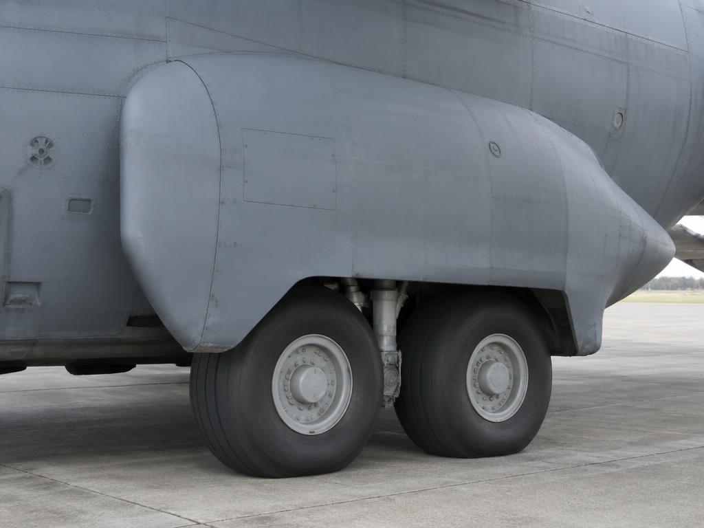
Tandem main gear retracting into the fuselage sponson
Tandem main gear retracting into the fuselage sponson · illustrative image

Retractable tricycle landing gear with tandem main wheels retracting into fuselage sponsons keeps the cargo floor low and unobstructed for roll-on/roll-off loading.

  • Each main gear has tandem (fore-and-aft) wheel pairs that retract up into fairings called sponsons bulging from the lower fuselage sides, rather than into the wing, keeping the wing structure simple and the cargo floor flat.
  • The nose gear retracts forward under the flight deck; all gear is hydraulically actuated with an emergency extension system if normal hydraulics fail.
  • Because the gear and sponsons sit outside the pressurised cargo floor structure, the cabin floor stays low to the ground and flat, letting vehicles and pallets drive straight on and off the rear ramp.
  • Low-pressure tyres and a rugged gear design are built for soft, unprepared and damaged runways typical of tactical airlift missions.

Pressurised Cargo Hold, Ramp & Systems ATA 21, 24, 25, 28, 29, 52, 53

Where it is

Location of Pressurised Cargo Hold, Ramp & Systems
Pressurised Cargo Hold, Ramp & Systems

What it looks like

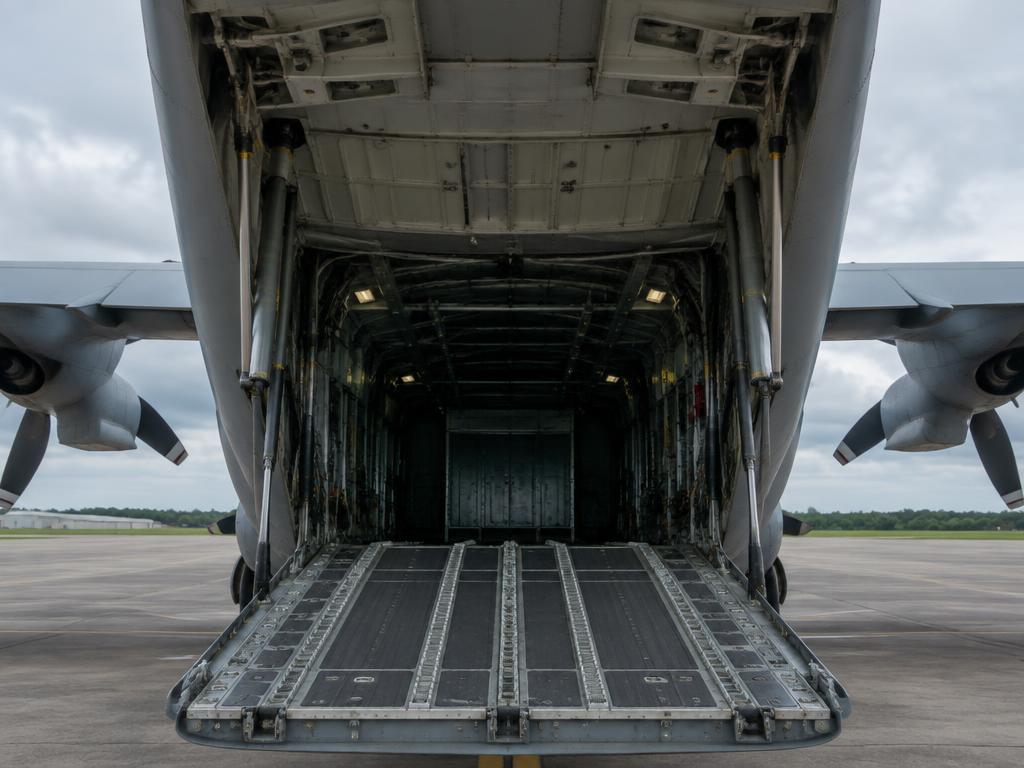
Rear cargo ramp and upper door with actuators
Rear cargo ramp and upper door with actuators · illustrative image

A pressurised cargo hold with a rear ramp and door, paratroop doors and roller/tie-down floor systems supports cargo, vehicles, paratroops and aerial delivery missions.

  • The cargo hold is pressurised for crew and passenger comfort at altitude, with bleed air supplying air conditioning and pressurisation from the engines (or the APU on the ground).
  • The rear ramp and door can open in flight for airdrop of cargo (Container Delivery System, CDS) or paratroops, and the ramp can also be lowered on the ground for straight-in vehicle loading.
  • Paratroop doors on each side of the fuselage, aft of the wing, allow jumpers to exit without opening the full ramp, used for personnel airdrops.
  • The APU, located in the left main gear sponson area, provides electrical and pneumatic power on the ground for engine starts and systems checks without external support equipment.
  • Electrical power is 28 VDC plus 115 VAC 400 Hz, supplied by four engine-driven generators and an APU generator, giving redundancy across the four engines.
  • Hydraulics (utility, booster and auxiliary systems, approx. 3,000 psi) power flight controls, landing gear, the ramp/door and other systems.

Empennage & APU ATA 49, 55, 33

Where it is

Location of Empennage & APU
Empennage & APU

What it looks like

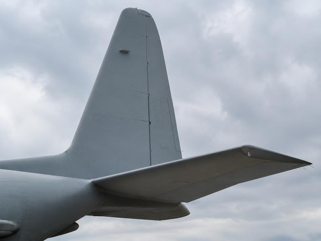
Fin, rudder, stabiliser and elevator
Fin, rudder, stabiliser and elevator · illustrative image

A conventional tail with powered elevator, rudder and horizontal stabiliser trim provides pitch and yaw control, while the APU supports ground and in-flight electrical/pneumatic needs.

  • The empennage carries the elevator and rudder, hydraulically powered with manual reversion, and a trimmable horizontal stabiliser for pitch trim across the aircraft's wide weight and CG range with cargo loads.
  • Because cargo position and airdrop sequencing shift the centre of gravity significantly in flight, the loadmaster and pilots monitor CG and trim carefully during cargo operations.
  • The APU, mounted in the left main gear sponson area, is a small gas-turbine engine providing electrical and pneumatic (bleed air) power independent of the four main engines.
  • The APU allows engine starts, air conditioning and systems checks without ground support equipment, valuable at austere or unprepared airfields with no ground power available.
7A

Annunciators & Fault Messages

Open the interactive fault finder →

GEN 1(2,3,4) FAILEngine-driven generator has tripped offline.
FUEL PRESS LO 1(2,3,4)Fuel pressure to the engine-driven pump is low (below 8 PSI).
ICE DETECTEDIcing conditions detected by the wing or empennage ice detectors.
APU FIREFire detected in the APU compartment (usually in the left main gear sponson area).
HYD OVERHEATHydraulic fluid temperature in Utility or Booster system exceeds limits.
AIRDROP SYS FAILMalfunction in the aerial delivery / cargo locking system.
MC 1(2) FAILOne of the two Mission Computers has failed.
CNI-MU 1(2) FAILCommunication, Navigation, Identification Management Unit (CNI-MU) keypad/display failure.
BLEED AIR LEAKHigh-temperature air leak detected in the bleed air ducting.
FADEC FAIL 1(2,3,4)Both channels of the FADEC on one engine have failed. Control of fuel and propeller is lost or severely degraded.
FUEL IMBALANCESignificant difference in fuel quantity between symmetrical tank pairs.
FIRE ENG 1Fire detected in the No.1 engine nacelle by the overheat/fire detection system.
PROP OVERSPEED 1(2,3,4)Propeller speed has exceeded 106% (approx. 1082 RPM). High risk of structural failure or loss of control.
PROP FEATHER FAILPropeller failed to feather following an engine shutdown or manual feather command.
UTIL HYD PRESS LOUtility hydraulic system pressure below 2500 PSI (Normal 3000 PSI).
BOOST HYD PRESS LOBooster hydraulic system pressure below 2500 PSI.
GEAR UNSAFEOne or more landing gear are not in the commanded position (unlocked or in transit).
RAMP/DOOR UNSAFECargo ramp or door is not fully closed and locked in flight.
CABIN ALTITUDECabin altitude above 10,000 ft (warning) or 13,000 ft.
ENG 1(2,3,4) OIL PRESS LOEngine oil pressure below 35 PSI in the gearbox or power section.
PROP OIL PRESS LOPropeller hydraulic pressure is low; pitch control may be degraded.
7B

Systems In Depth (engine, gear, controls…)

Deep dive · ATA 21

Air Conditioning and Pressurization

Bleed Air Supply

High-pressure bleed air is extracted from the 14th stage of the engine compressors or from the APU.

This air is used for cabin pressurization, air conditioning, and anti-icing.

AC PacksDual Air Cycle Machines
Max Cabin Altapprox. 8,000 ft at 35,000 ft
Differential Pressureapprox. 7.5 psi max

Air Conditioning Packs

Two independent air cycle packs (Left and Right) cool the hot bleed air. The conditioned air is then distributed to the cockpit and cargo compartment.

The 'Underfloor' heating system provides additional warmth for the cargo hold during high-altitude flight.

Pressurization Control

Managed by a digital controller that regulates the outflow valves. It maintains a comfortable cabin altitude and rate of change during climb and descent.

Deep dive · ATA 22

Auto Flight — AFCS and Autothrottle

Automatic Flight Control System (AFCS)

The AFCS provides autopilot and flight director functions. It is fully integrated with the CNI-MU and Mission Computers.

Modes include Heading Hold, Altitude Hold, LNAV (Lateral Navigation), and VNAV (Vertical Navigation).

Autothrottle

The C-130J features an autothrottle system that adjusts the power levers to maintain a target airspeed or torque setting. This is particularly useful during long-range cruise and tactical approaches.

ChannelsDual Redundant
AutolandCAT II capable (typical)

Low-Level Flight

The AFCS can be coupled with Terrain Following / Terrain Avoidance (TF/TA) radar for low-level tactical missions in IMC.

Deep dive · ATA 24

Electrical Power System — AC and DC Generation

AC Power Architecture

The C-130J uses a 115/200 VAC, 3-phase, 400 Hz system as its primary power source. It features four engine-driven Integrated Drive Generators (IDGs), each rated at 60/90 kVA. A fifth generator of the same rating is driven by the APU.

The distribution is managed through four main AC buses: Left, Essential, Main, and Right. Under normal operations, each engine-driven generator powers its respective bus, with the APU generator available as a backup on the ground or in flight.

The system includes an automatic bus-tie feature, allowing a single operating generator to power the entire AC system if necessary, though load shedding may occur to stay within generator limits.

Primary AC System115/200 VAC, 400 Hz, 3-phase
IDG Rating60/90 kVA each
APU Generator60/90 kVA
Bus LogicAutomatic Bus Tie / Priority-based distribution

DC Power System

28 VDC power is provided by four Transformer-Rectifier (TR) units, which convert 115 VAC to DC. These feed the DC buses: Essential, Main, and Isolated.

Two 24-volt, 50-amp-hour batteries provide emergency power for critical flight instruments, the CNI system, and engine starting (via the APU). The Isolated DC bus is specifically designed to be powered by the batteries in the event of a total TR failure.

DC System28 VDC
TR Units4 x conversion units
Batteries2 x 24V 50Ah NiCd
Emergency BusIsolated DC Bus

Power Distribution and Management

The electrical system is monitored and controlled by the Mission Computers and displayed on the MFDs via the CNI system. Circuit breakers are located in the cockpit (overhead and side panels) and in the cargo compartment.

Warning · Avoid prolonged battery-only operation to prevent deep discharge, which can inhibit APU starting and critical avionics.

Deep dive · ATA 26

Fire Protection — Detection and Suppression

Engine Fire Detection

Continuous-loop sensing elements (Pneumatic or Thermistor) are installed in each engine nacelle. A fire triggers the MASTER WARNING, an aural alert, and the engine fire handle light.

Extinguishing System

Two fire extinguisher bottles (HRD - High Rate Discharge) are provided for the four engines. A cross-feed manifold allows both bottles to be discharged into the same engine if needed.

Extinguishing AgentHalon 1301 or equivalent
APU Bottle1 dedicated bottle
Cargo CompartmentHandheld extinguishers + smoke detectors

Cargo Smoke Detection

Photoelectric smoke detectors are located throughout the cargo compartment ceiling. Cautions are displayed on the MFD and loadmaster panel.

Warning · Pulling an engine fire handle shuts off fuel, hydraulics, and bleed air to that engine, and feathers the propeller.

Deep dive · ATA 27

Flight Controls — Hydraulic Boost and Flaps

Primary Controls

Ailerons, Elevators, and Rudder are conventionally operated but hydraulically boosted. The boost units reduce pilot effort while maintaining 'feel'.

The system is powered by the Utility and Booster hydraulic systems. In the event of dual hydraulic failure, the aircraft can be flown manually, though control forces are significantly higher.

System Pressureapprox. 3,000 psi
Power SourcesUtility and Booster systems
Manual ReversionAvailable for primary controls

Flap System

The C-130J uses large Fowler-type flaps for high lift. They are operated by a central hydraulic motor and a system of torque tubes and jackscrews.

Flap settings are: 0%, 50% (takeoff/approach), and 100% (landing). An asymmetry detection system stops flap movement if a deviation between left and right sides is detected.

Trim Systems

Electric trim is provided for all three axes. The elevator trim is critical for longitudinal stability across the wide CG range of the C-130J.

Warning · Aileron or rudder boost failure requires immediate speed reduction and following the boost-off landing procedures.

Deep dive · ATA 28

Fuel System — Management and Distribution

Tank Configuration

The C-130J features a highly versatile fuel system with internal wing tanks and optional external tanks. The internal capacity is approx. 45,900 lb (approx. 6,750 gallons).

Standard tanks include four integral wing tanks (Main 1-4) and two auxiliary bladder-type tanks in the center wing section. External pylon-mounted tanks (1,400 gallons each) can be fitted for extended range or ferry missions.

Total Internal Fuelapprox. 45,900 lb
Main Tanks (1 & 4)approx. 8,300 lb each
Main Tanks (2 & 3)approx. 7,600 lb each
Auxiliary Tanksapprox. 5,800 lb each
External Tanksapprox. 9,000 lb each (optional)

Supply and Transfer

Each engine is normally fed from its respective main tank via a boost pump. Cross-feed valves allow any tank to feed any engine or multiple engines.

Fuel transfer is accomplished using the cross-feed manifold. Transfer pumps in the auxiliary and external tanks move fuel into the main tanks or directly to the engines.

The system is managed through the Fuel Management System (FMS) page on the MFD, which provides real-time quantity, flow, and valve status.

  1. 1.Open cross-feed valves for the desired manifold path.
  2. 2.Turn on the transfer pump in the source tank (Aux or External).
  3. 3.Monitor Main tank quantities to prevent overfilling/venting.
  4. 4.Select 'Auto-Transfer' if using the Mission Computer logic for fuel balancing.

Refueling

Single-point pressure refueling is conducted through a receptacle in the right main landing gear sponson. Gravity refueling is possible through overwing caps on all tanks.

Warning · Monitor fuel balance carefully; excessive asymmetry can impact lateral control and structural limits during high-G maneuvers.

Deep dive · ATA 29

Hydraulic Systems — Utility, Booster, and Aux

Architecture

The C-130J features three independent 3,000 psi hydraulic systems: Utility, Booster, and Auxiliary.

Utility System: Powered by pumps on engines 1 and 2. Operates landing gear, brakes, nose wheel steering, flaps, and half of the flight control boost.

Booster System: Powered by pumps on engines 3 and 4. Operates the other half of the flight control boost units.

Auxiliary System: Powered by an electric motor-driven pump. Provides pressure for cargo ramp and door operation and emergency brake pressure.

Nominal Pressure3,000 psi
Utility PumpsEngines 1 & 2
Booster PumpsEngines 3 & 4
Aux PumpElectric motor (AC)

Emergency Procedures

A hand pump is provided for the Auxiliary system to operate the ramp and door or charge brake accumulators if all electrical and engine power is lost.

Crossover valves (ground use only) allow one system to pressurize another for maintenance checks.

Ground Operations

The Auxiliary pump is typically used for ground maintenance of flaps and gear doors without running engines.

Warning · Ensure all personnel are clear of gear doors and flaps before activating the Auxiliary pump.

Deep dive · ATA 30

Ice and Rain Protection

Engine and Propeller Anti-Ice

Engine inlets are heated by engine bleed air. Propeller blades are de-iced by electro-thermal elements (monitored by the FADEC).

Wing/Tail HeatBleed air (Pneumatic)
Propeller HeatElectrical
WindshieldElectrical NESA

Wing and Empennage Ice Protection

Leading edges of the wings and tail surfaces are heated by bleed air from the main manifold. The system is divided into zones and controlled by the Ice Protection panel.

Windshield and Pitot Heat

The cockpit windshields use an integrated electrical heating layer (NESA) for both anti-icing and bird-strike protection (by keeping the vinyl layer flexible).

Pitot tubes, static ports, and AOA sensors are electrically heated.

Warning · Prolonged use of wing anti-ice on the ground can lead to structural overheating; use is restricted to flight or brief ground tests.

Deep dive · ATA 32

Landing Gear and Braking System

Gear Configuration

Retractable tricycle gear. The main gear consists of four wheels in a tandem configuration (two on each side) that retract into fuselage sponsons.

The nose gear is a dual-wheel unit that retracts forward into the nose section.

Tire Pressure (Main)approx. 100-110 psi (varies with weight)
Tire Pressure (Nose)approx. 60-80 psi
Steering Limitapprox. 60 degrees (low speed)

Braking System

Multi-disc hydraulic brakes are fitted to all four main wheels. The system includes an anti-skid unit that prevents wheel lockup on slippery runways.

Emergency braking is provided by the Auxiliary hydraulic system via a dedicated accumulator.

Nose Wheel Steering

Steering is controlled by a tiller in the cockpit (pilot side) or by rudder pedal inputs (limited range). It is powered by the Utility hydraulic system.

Deep dive · ATA 34

Navigation and Avionics — CNI-MU and HUD

Glass Cockpit Architecture

The C-130J features a 'glass' cockpit with four primary MFDs (Multi-Function Displays) and two HUDs (Head-Up Displays).

The CNI-MU (Communication, Navigation, Identification - Management Unit) serves as the primary interface for flight planning, radio tuning, and system monitoring.

HUDs2 x Flight Dynamics/Elbit
MFDs4 x 6x8 inch Color Displays
Mission ComputersDual Redundant
NavigationGPS / INS / TACAN / VOR / ILS

Head-Up Display (HUD)

The HUD provides critical flight data (airspeed, altitude, attitude, heading) directly in the pilot's line of sight, which is essential for tactical low-level flying and low-visibility landings.

Mission Computers

Dual Mission Computers (MCs) act as the 'brain' of the aircraft, integrating data from all sensors and systems to provide a unified tactical and flight picture.

Deep dive · ATA 36

Pneumatic System — Bleed Air Manifold

Bleed Air Manifold

A common manifold runs along the center wing, connecting all four engines and the APU. This manifold supplies air for air conditioning, pressurization, and anti-icing.

Isolation valves allow the manifold to be split into sections, ensuring that a leak in one area does not disable the entire system.

Max Temperatureapprox. 600 °F
Operating Pressureapprox. 45-70 psi
Sources4 Engines + APU + External Air

External Air

A ground air connection allows the use of a ground cart (huffer) for engine starting and cabin cooling without using the APU.

Leak Detection

A 'Bleed Air Overheat' or 'Leak' warning is triggered by sensing loops along the ducting. The affected engine or manifold section must be isolated immediately per the QRH.

Deep dive · ATA 49

Auxiliary Power Unit (APU) — AlliedSignal/Honeywell

APU Role and Location

The APU is a small gas turbine engine located in the left main landing gear sponson. It provides ground power (AC and DC) and bleed air for engine starting and air conditioning.

It can be operated in flight for emergency electrical power.

APU ModelAlliedSignal GTCP85-129 series (or similar)
Generator Output60/90 kVA
Start SourceAircraft Battery
Fuel SourceNo. 2 Main Tank

Start Cycle

The APU is started electrically using the aircraft batteries. Once at 95-100% RPM, it can accept electrical loads and bleed air demands.

  1. 1.Check APU fire bottle pressure.
  2. 2.Switch APU Master to START (momentary).
  3. 3.Monitor EGT and RPM rise.
  4. 4.Engage APU Generator once stabilized.

Fire Protection

The APU compartment is equipped with a dedicated fire detection loop and a single-shot extinguisher bottle. An auto-shutdown feature triggers if a fire or certain internal faults are detected.

Deep dive · ATA 52

Doors and Ramps — Cargo and Personnel

Cargo Ramp and Door

The aft fuselage features a large ramp and a separate door. The ramp can be lowered to the ground for loading or to a horizontal position for airdrop operations.

The system is hydraulically operated by the Auxiliary system (or hand pump).

Ramp Capacity (Ground)approx. 25,000 lb
Airdrop Speed Limitapprox. 150 KIAS (typical)
Control PanelAft Loadmaster station

Paratroop Doors

Two paratroop doors are located on the aft fuselage sides. They are manually operated and slide upward. Wind deflectors are deployed forward of the doors during jumps.

Crew Entrance Door

A plug-type door on the forward left side of the fuselage. It includes an integrated ladder for entry and exit.

Warning · The ramp and door must be properly locked before pressurization. A 'RAMP UNLOCKED' caution requires immediate investigation.

Deep dive · ATA 61

Propeller System — Dowty R391

Construction and Pitch Control

The C-130J is equipped with four Dowty R391 six-blade composite propellers. The blades feature a scimitar shape for high efficiency and reduced noise.

Pitch control is fully integrated with the FADEC (Full Authority Digital Engine Control). There is no mechanical linkage between the cockpit and the propeller governor.

The system provides constant speed, feathering, and reversing capabilities. Reversing is used for ground deceleration and tactical maneuvers (backing up).

Propeller TypeDowty R391, 6-blade
Blade MaterialCarbon fiber composite
Control SystemDual-channel FADEC
Diameter13.5 ft (approx.)

Operational Modes

Alpha Range: Flight range (flight idle to max power). Propeller speed is maintained at a constant RPM (typically 100%).

Beta Range: Ground range (flight idle to full reverse). The pilot has direct control over the propeller blade angle via the power levers.

  1. 1.Feathering: Automatically initiated by FADEC on engine failure or manually via the fire handle.
  2. 2.Synchrophasing: The Mission Computer adjusts the relative blade positions between propellers to minimize cabin noise and vibration.
  3. 3.De-icing: Electro-thermal heating elements in the blade leading edges prevent ice buildup.

Reversing Operations

Unlike jet aircraft with thrust reversers, the C-130J changes the pitch of the propeller blades into a negative angle. This generates significant reverse thrust.

Warning · Inadvertent propeller reversal in flight is prevented by redundant FADEC interlocks and physical flight idle stops.

Deep dive · ATA 71

Power Plant — Rolls-Royce AE 2100D3

Engine Overview

The AE 2100D3 is a high-performance turboprop engine rated at approx. 4,590 shp. It consists of a 14-stage axial compressor, an annular combustor, and a two-stage high-pressure turbine driving the compressor.

A two-stage power turbine drives the propeller through a reduction gearbox (RGB) with a ratio of approx. 14:1.

Engine TypeTwo-spool Turboprop
Takeoff Powerapprox. 4,590 shp
Compressor Stages14-stage axial
Gearbox Ratioapprox. 14 : 1
Max ITTapprox. 850 °C (takeoff)

FADEC Control

Each engine and propeller combination is controlled by a dual-channel FADEC. The FADEC optimizes fuel flow and propeller pitch based on power lever position, altitude, and ambient conditions.

It provides automatic engine starting, auto-feathering, and engine limit protection (torque, ITT, and RPM).

Engine Indicating

Engine data (Torque, HP, NP, NG, ITT, Fuel Flow) is processed by the NIU (Nacelle Interface Unit) and sent to the Mission Computers for display on the HUD and MFDs.

Deep dive · ATA 73

Engine Fuel and Control — FADEC and Fuel Metering

FADEC System

The C-130J utilizes a dual-channel FADEC (Full Authority Digital Engine Control) to manage engine performance. It eliminates the need for a flight engineer by automating most engine control functions.

The FADEC monitors engine parameters and adjusts fuel flow and propeller pitch to maintain the commanded power setting while staying within safe operating limits.

Fuel Metering Unit (FMU)

The FMU is a hydromechanical unit controlled by the FADEC. It schedules fuel to the engine nozzles based on electronic signals. It includes a high-pressure pump and a shut-off valve.

Deep dive · ATA 77

Engine Indicating — NIU and MFD Integration

Nacelle Interface Unit (NIU)

Each engine has an NIU that collects analog data from sensors (temp, pressure, vibration) and converts it to digital data for the Mission Computers.

This ensures that critical engine health data is accurately represented on the cockpit displays.

Deep dive · ATA 79

Engine Oil System — Lubrication and Cooling

Oil Distribution

A self-contained dry-sump system provides lubrication and cooling for the engine bearings and the reduction gearbox.

An air/oil cooler, located in the nacelle, uses ram air to maintain optimal oil temperature.

8A

Maintenance Task Cards

Main Battery Voltage and Security Check

ATA 24 · Weekly / Before flight

Access · Nose Compartment / Battery Rack

Tools & materials · Multimeter · Wrench set

Warning · NiCd batteries can produce explosive gases during charging. Ensure adequate ventilation.

  1. 1.Access the battery compartment in the nose.
  2. 2.Verify the batteries are securely mounted and the connectors are tight.
  3. 3.Measure the open-circuit voltage of each battery; it should be above 24V.
  4. 4.Check the battery case for signs of swelling, leakage, or corrosion.
  5. 5.Inspect the vent tubes for obstructions.
  6. 6.Verify the Battery Master switch operation in the cockpit.
Min Voltage24.0 VDC
Capacity50 Ah per battery

Ref: C-130J AMM Ch. 24 / Battery Maintenance

Fuel Tank Sump Draining (Water Check)

ATA 28 · Daily / Before first flight

Access · Underwing drain valves

Tools & materials · Fuel sampler cup · Waste fuel container

Warning · Fuel is flammable. Ensure aircraft is grounded during draining. No smoking or open flames.

  1. 1.Locate the sump drain valves at the lowest point of each wing tank (Main, Aux, External).
  2. 2.Place the sampler cup under the valve and press upward to release fuel.
  3. 3.Observe the fuel sample for water bubbles, sediment, or cloudiness (microbial growth).
  4. 4.Continue draining until a clean, water-free sample is obtained.
  5. 5.Dispose of waste fuel in an approved hazardous waste container.
  6. 6.Ensure the drain valve closes completely and does not drip.
Acceptable SampleClear and bright, no visible water

Ref: C-130J AMM Ch. 28 / Fuel Quality Control

Utility Hydraulic Reservoir Servicing

ATA 29 · Daily / On condition

Access · Right Main Gear Sponson Service Panel

Tools & materials · MIL-PRF-83282 Hydraulic Fluid · Hand pump · Safety goggles

Warning · Hydraulic fluid is under high pressure. Wear eye protection and avoid skin contact.

  1. 1.Check the reservoir quantity indicator on the service panel.
  2. 2.Ensure all accumulators are discharged or at pre-charge pressure for accurate reading.
  3. 3.Connect the hand pump to the Utility system service coupling.
  4. 4.Pump fluid until the indicator reaches the 'FULL' mark.
  5. 5.Disconnect the pump and clean any spilled fluid.
  6. 6.Perform a functional check of a hydraulic sub-system (e.g., flaps) if air ingestion is suspected.
System Pressure3,000 psi
Fluid TypeMIL-PRF-83282 (Fire resistant)

Ref: C-130J AMM Ch. 29

Main Landing Gear Tire Pressure Check

ATA 32 · Daily / Before first flight

Access · Main Landing Gear Sponsons

Tools & materials · Calibrated tire pressure gauge (0-300 psi) · Nitrogen service cart

Warning · Stand to the side of the tire when servicing. Never exceed max inflation pressure.

  1. 1.Ensure tires are 'cold' (at least 3 hours after last flight).
  2. 2.Remove valve stem caps from all four main gear tires.
  3. 3.Measure pressure and compare against the weight-based chart in the AMM.
  4. 4.If pressure is low, service with dry nitrogen only.
  5. 5.Inspect tires for cuts, flat spots, or excessive wear (cords showing).
  6. 6.Replace valve caps and hand-tighten.
Nominal Pressureapprox. 100-110 psi (at MTOW)
Max Deviation5% between tires on same side

Ref: C-130J AMM Ch. 32 / Tire Servicing Data

Brake Wear Indicator Check

ATA 32 · Daily / Pre-flight

Access · Main Wheel Assemblies

Tools & materials · Flashlight · Ruler or depth gauge

Warning · Do not touch hot brakes after flight. Allow to cool before inspection.

  1. 1.Park the aircraft on a level surface and set the parking brake (Utility pressure applied).
  2. 2.Locate the wear indicator pins on each of the four main brake assemblies.
  3. 3.Measure the protrusion of the pin from the brake housing.
  4. 4.If the pin is flush with the housing, the brake stack must be replaced.
  5. 5.Check for signs of hydraulic leaks around the piston area.
  6. 6.Inspect the brake discs for excessive scoring or heat discoloration.
Min Protrusion0.0 inches (flush)

Ref: C-130J AMM Ch. 32 / Brake Inspection

Liquid Oxygen (LOX) System Servicing

ATA 35 · As required / Pre-mission

Access · Left forward fuselage LOX panel

Tools & materials · LOX servicing cart · Cryogenic gloves · Face shield

Warning · Liquid oxygen is extremely cold (-297 F) and a powerful oxidizer. Keep all grease and oil away from oxygen equipment.

  1. 1.Check the oxygen quantity on the cockpit gauge.
  2. 2.Don full cryogenic protective gear (gloves, apron, face shield).
  3. 3.Connect the LOX cart hose to the aircraft filler valve.
  4. 4.Open the vent valve on the aircraft panel.
  5. 5.Start LOX transfer and monitor the vent for a steady stream of liquid (indicating full).
  6. 6.Close the vent valve, stop transfer, and disconnect the hose.
  7. 7.Wait for the connection to defrost before replacing the cap.
LOX Capacityapprox. 25 Liters
Operating Pressureapprox. 300 psi

Ref: C-130J AMM Ch. 35 / LOX Servicing Procedures

APU Lubrication System Servicing

ATA 49 · 50-hour check / As required

Access · Left Main Gear Sponson APU Compartment

Tools & materials · MIL-PRF-23699 Oil · Wrench set

Warning · Hot APU components can cause severe burns.

  1. 1.Ensure the APU is shut down and cooled (at least 15 minutes).
  2. 2.Open the APU access door.
  3. 3.Check the oil level on the APU gearbox dipstick.
  4. 4.Add oil as required to bring the level to the 'FULL' mark.
  5. 5.Reinstall the dipstick and ensure it is properly seated.
  6. 6.Check the magnetic chip detector for any metal particles.
Oil Capacityapprox. 4 quarts
Chip DetectorNo significant metal flakes allowed

Ref: C-130J AMM Ch. 49 / APU Maintenance Manual

Cargo Ramp and Door Operational Test

ATA 52 · A-Check / Before airdrop missions

Access · Aft Cargo Compartment

Tools & materials · None (System test)

Warning · Stay clear of moving ramp components. Use a spotter when operating the ramp on the ground.

  1. 1.Clear the area behind and under the ramp.
  2. 2.Apply Auxiliary hydraulic pressure (Electric Pump ON).
  3. 3.From the loadmaster panel, select 'OPEN' for the cargo door.
  4. 4.Lower the ramp to the 'GROUND' position and check for smooth operation.
  5. 5.Raise the ramp to the 'HORIZONTAL' position and verify the locks engage.
  6. 6.Close the door and ramp, ensuring all 'UNLOCKED' lights extinguish.
  7. 7.Check the ADS (Aerial Delivery System) rails for security.
Cycle TimeWithin AMM specifications
Lock IndicationPositive green lights

Ref: C-130J AMM Ch. 52

Propeller Blade Visual Inspection (Dowty R391)

ATA 61 · Pre-flight / 50-hour check

Access · Ground level

Tools & materials · Flashlight · Magnifying glass · Measuring scale

Warning · Composite blades are susceptible to impact damage. Any sign of lightning strike requires immediate grounding.

  1. 1.Inspect all six blades on each propeller for nicks, scratches, or delamination.
  2. 2.Check the leading edge de-icing boots for erosion or lifting.
  3. 3.Inspect the hub area for signs of hydraulic fluid (oil) leaks.
  4. 4.Verify the security of the spinner and mounting bolts.
  5. 5.Document any damage found and compare against the Structural Repair Manual (SRM) limits.
Leading Edge NicksMax depth per SRM
DelaminationNone allowed in critical zones

Ref: C-130J AMM Ch. 61 / Dowty R391 Component Maintenance Manual

Engine Oil Servicing (AE 2100D3)

ATA 79 · Daily / After each flight

Access · Engine Nacelle Side Panels

Tools & materials · MIL-PRF-23699 Lubricating Oil · Lint-free cloths · Oil servicing cart or funnel

Warning · Use only approved synthetic oil. Do not mix different brands or types.

  1. 1.Check oil level within 30 minutes of engine shutdown for accurate reading.
  2. 2.Open the oil service access door on the nacelle.
  3. 3.Observe the sight gauge; if level is below 'FULL', servicing is required.
  4. 4.Remove filler cap and add oil until the 'FULL' mark is reached.
  5. 5.Ensure the filler cap is securely locked and the access door is latched.
  6. 6.Record the quantity of oil added in the aircraft logbook.
Total Capacityapprox. 12 US gallons
Refill levelBelow 'FULL' on sight glass

Ref: C-130J maintenance manual Ch. 12

8

Maintenance Overview (by ATA)

ATA 21 — Air Conditioning & Pressurization

  • Ramp, door and paratroop door actuator and seal inspections per the maintenance manual.
  • Pressurisation and bleed air system leak and function checks.
  • Electrical generator, bus and APU function checks at scheduled intervals.
  • Hydraulic reservoir, filter and pressure checks across utility, booster and auxiliary systems.

ATA 22 — Auto Flight

  • MFD, HUD and mission computer built-in test (BIT) checks before flight per the C-130J Flight Manual.
  • Avionics software configuration verified against the aircraft's certified load per the maintenance manual.
  • Pitot-static and air data system checks at scheduled intervals.

ATA 23 — Communications

  • MFD, HUD and mission computer built-in test (BIT) checks before flight per the C-130J Flight Manual.
  • Avionics software configuration verified against the aircraft's certified load per the maintenance manual.
  • Pitot-static and air data system checks at scheduled intervals.

ATA 24 — Electrical Power

  • Ramp, door and paratroop door actuator and seal inspections per the maintenance manual.
  • Pressurisation and bleed air system leak and function checks.
  • Electrical generator, bus and APU function checks at scheduled intervals.
  • Hydraulic reservoir, filter and pressure checks across utility, booster and auxiliary systems.

ATA 25 — Equipment / Furnishings

  • Ramp, door and paratroop door actuator and seal inspections per the maintenance manual.
  • Pressurisation and bleed air system leak and function checks.
  • Electrical generator, bus and APU function checks at scheduled intervals.
  • Hydraulic reservoir, filter and pressure checks across utility, booster and auxiliary systems.

ATA 27 — Flight Controls

  • Flap track, actuator and rigging inspections per the maintenance manual.
  • Flight control cable, hydraulic actuator and surface inspections at scheduled intervals.
  • Wing fuel tank, vent and crossfeed system leak and function checks.

ATA 28 — Fuel

  • Flap track, actuator and rigging inspections per the maintenance manual.
  • Flight control cable, hydraulic actuator and surface inspections at scheduled intervals.
  • Wing fuel tank, vent and crossfeed system leak and function checks.
  • Ramp, door and paratroop door actuator and seal inspections per the maintenance manual.
  • Pressurisation and bleed air system leak and function checks.
  • Electrical generator, bus and APU function checks at scheduled intervals.
  • Hydraulic reservoir, filter and pressure checks across utility, booster and auxiliary systems.

ATA 29 — Hydraulic Power

  • Ramp, door and paratroop door actuator and seal inspections per the maintenance manual.
  • Pressurisation and bleed air system leak and function checks.
  • Electrical generator, bus and APU function checks at scheduled intervals.
  • Hydraulic reservoir, filter and pressure checks across utility, booster and auxiliary systems.

ATA 31 — Indicating / Recording

  • MFD, HUD and mission computer built-in test (BIT) checks before flight per the C-130J Flight Manual.
  • Avionics software configuration verified against the aircraft's certified load per the maintenance manual.
  • Pitot-static and air data system checks at scheduled intervals.

ATA 32 — Landing Gear

  • Landing gear retraction/extension function and rigging checks per the maintenance manual.
  • Tyre, brake and wheel bearing inspections at scheduled intervals.
  • Sponson structure and gear door inspections for corrosion and damage.

ATA 33 — Lights

  • Empennage control surface, cable and actuator inspections per the maintenance manual.
  • APU start, generator and bleed air function checks at scheduled intervals.
  • Stabiliser trim actuator and position indication checks.

ATA 34 — Navigation

  • MFD, HUD and mission computer built-in test (BIT) checks before flight per the C-130J Flight Manual.
  • Avionics software configuration verified against the aircraft's certified load per the maintenance manual.
  • Pitot-static and air data system checks at scheduled intervals.

ATA 49 — Airborne Auxiliary Power (APU)

  • Empennage control surface, cable and actuator inspections per the maintenance manual.
  • APU start, generator and bleed air function checks at scheduled intervals.
  • Stabiliser trim actuator and position indication checks.

ATA 52 — Doors

  • Ramp, door and paratroop door actuator and seal inspections per the maintenance manual.
  • Pressurisation and bleed air system leak and function checks.
  • Electrical generator, bus and APU function checks at scheduled intervals.
  • Hydraulic reservoir, filter and pressure checks across utility, booster and auxiliary systems.

ATA 53 — Fuselage

  • Ramp, door and paratroop door actuator and seal inspections per the maintenance manual.
  • Pressurisation and bleed air system leak and function checks.
  • Electrical generator, bus and APU function checks at scheduled intervals.
  • Hydraulic reservoir, filter and pressure checks across utility, booster and auxiliary systems.

ATA 55 — Stabilizers

  • Empennage control surface, cable and actuator inspections per the maintenance manual.
  • APU start, generator and bleed air function checks at scheduled intervals.
  • Stabiliser trim actuator and position indication checks.

ATA 57 — Wings

  • Flap track, actuator and rigging inspections per the maintenance manual.
  • Flight control cable, hydraulic actuator and surface inspections at scheduled intervals.
  • Wing fuel tank, vent and crossfeed system leak and function checks.

ATA 61 — Propellers

  • FADEC fault history download and trend monitoring per the maintenance manual.
  • Propeller blade, hub and pitch-change mechanism inspections per ATA Chapter 61.
  • Engine hot-section borescope inspections per the AE 2100D3 engine manual.
  • Engine and gearbox oil, chip detector and vibration monitoring at scheduled intervals.

ATA 71 — Power Plant

  • FADEC fault history download and trend monitoring per the maintenance manual.
  • Propeller blade, hub and pitch-change mechanism inspections per ATA Chapter 61.
  • Engine hot-section borescope inspections per the AE 2100D3 engine manual.
  • Engine and gearbox oil, chip detector and vibration monitoring at scheduled intervals.

ATA 72 — Engine

  • FADEC fault history download and trend monitoring per the maintenance manual.
  • Propeller blade, hub and pitch-change mechanism inspections per ATA Chapter 61.
  • Engine hot-section borescope inspections per the AE 2100D3 engine manual.
  • Engine and gearbox oil, chip detector and vibration monitoring at scheduled intervals.

ATA 73 — Engine Fuel & Control

  • FADEC fault history download and trend monitoring per the maintenance manual.
  • Propeller blade, hub and pitch-change mechanism inspections per ATA Chapter 61.
  • Engine hot-section borescope inspections per the AE 2100D3 engine manual.
  • Engine and gearbox oil, chip detector and vibration monitoring at scheduled intervals.

ATA 74 — Ignition

  • FADEC fault history download and trend monitoring per the maintenance manual.
  • Propeller blade, hub and pitch-change mechanism inspections per ATA Chapter 61.
  • Engine hot-section borescope inspections per the AE 2100D3 engine manual.
  • Engine and gearbox oil, chip detector and vibration monitoring at scheduled intervals.

ATA 76 — Engine Controls

  • MFD, HUD and mission computer built-in test (BIT) checks before flight per the C-130J Flight Manual.
  • Avionics software configuration verified against the aircraft's certified load per the maintenance manual.
  • Pitot-static and air data system checks at scheduled intervals.
  • FADEC fault history download and trend monitoring per the maintenance manual.
  • Propeller blade, hub and pitch-change mechanism inspections per ATA Chapter 61.
  • Engine hot-section borescope inspections per the AE 2100D3 engine manual.
  • Engine and gearbox oil, chip detector and vibration monitoring at scheduled intervals.

ATA 77 — Engine Indicating

  • MFD, HUD and mission computer built-in test (BIT) checks before flight per the C-130J Flight Manual.
  • Avionics software configuration verified against the aircraft's certified load per the maintenance manual.
  • Pitot-static and air data system checks at scheduled intervals.
  • FADEC fault history download and trend monitoring per the maintenance manual.
  • Propeller blade, hub and pitch-change mechanism inspections per ATA Chapter 61.
  • Engine hot-section borescope inspections per the AE 2100D3 engine manual.
  • Engine and gearbox oil, chip detector and vibration monitoring at scheduled intervals.

ATA 79 — Oil

  • FADEC fault history download and trend monitoring per the maintenance manual.
  • Propeller blade, hub and pitch-change mechanism inspections per ATA Chapter 61.
  • Engine hot-section borescope inspections per the AE 2100D3 engine manual.
  • Engine and gearbox oil, chip detector and vibration monitoring at scheduled intervals.

ATA 80 — Starting

  • FADEC fault history download and trend monitoring per the maintenance manual.
  • Propeller blade, hub and pitch-change mechanism inspections per ATA Chapter 61.
  • Engine hot-section borescope inspections per the AE 2100D3 engine manual.
  • Engine and gearbox oil, chip detector and vibration monitoring at scheduled intervals.

EDUCATIONAL USE ONLY. Content is summarised from manufacturer documentation for learning. It is not approved flight or maintenance data. Always use the current, aircraft-specific POH/AFM, FCOM, QRH, AMM and operator procedures.