Sections menu
Lockheed Martin C-130J Super Hercules · Live schematics
System schematics
Operate the switches and introduce failures — the diagram shows where fuel, power or pressure flows and what it means for the pilot.
Unverified — check your manualText on this page is written from general knowledge. Figures marked ✓ are checked against official FAA/EASA data.See verified data
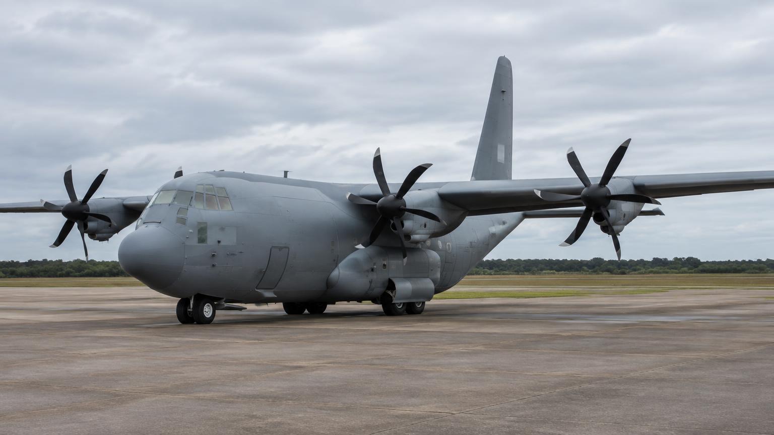
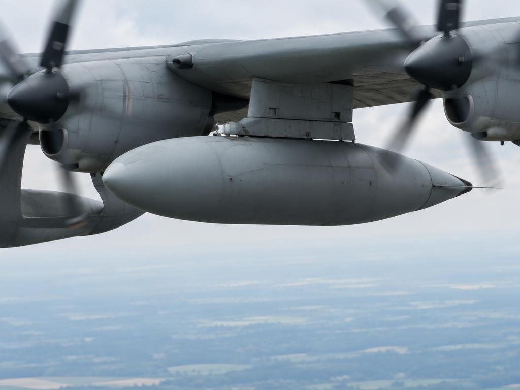
ATA 28 Fuel · Total capacity approx. 45,900 lb (J). 4 main wing tanks, 2 internal auxiliary tanks, and 2 external pylon tanks. A crossfeed manifold allows any tank to feed any engine.
Where it is
Fuel System
What it looks like
Controls
Crossfeed
T1 Pump
T2 Pump
T3 Pump
T4 Pump
Inject failures
What this means
How it works
- The fuel system is designed to provide a continuous supply of fuel to the four engines under all flight conditions.
- Fuel is stored in six internal wing tanks (4 main, 2 auxiliary) and two external pylon tanks.
- A crossfeed manifold connects all tanks and engines, allowing any tank to feed any engine or any combination of engines.
- Submerged boost pumps in each tank provide positive pressure to the manifold, while engine-driven pumps provide the final high pressure for combustion.
How the parts work together
- In normal flight, each engine is fed from its respective main tank (e.g. Tank 1 feeds Engine 1) with crossfeed valves closed.
- During long-range missions, auxiliary and external tanks are depleted first by opening their respective valves and the crossfeed manifold.
- The FMS monitors fuel quantity and flow, providing alerts for low fuel or imbalances between the wings.
- Firewall shutoff valves can be closed from the cockpit to isolate an engine from the fuel supply in case of emergency.
What each part does
Click a box in the diagram or a part below to highlight it.
EDUCATIONAL USE ONLY. Content is summarised from manufacturer documentation for learning. It is not approved flight or maintenance data. Always use the current, aircraft-specific POH/AFM, FCOM, QRH, AMM and operator procedures.