ATA 21
Air Conditioning & Pressurisation
Two air-cycle packs condition engine or APU bleed air. A mixer unit blends pack and recirculated cabin air. Two cabin pressure controllers (CPC) automatically schedule the outflow valve.
Where it is
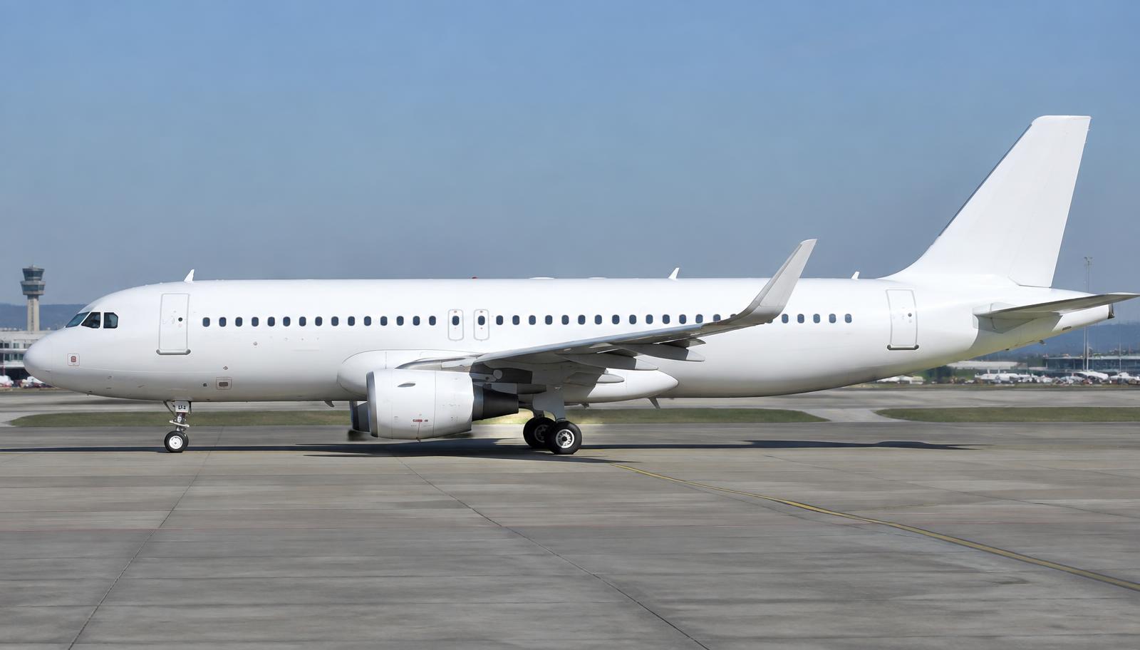
What it looks like
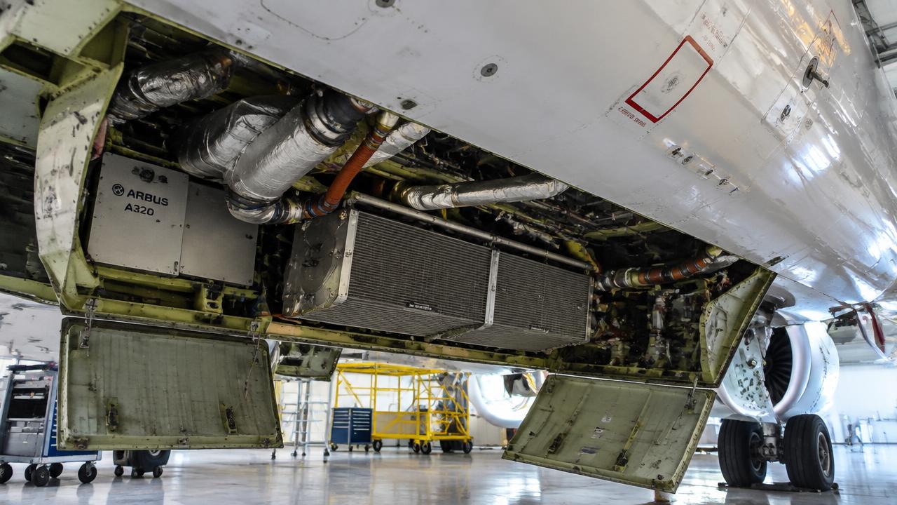
Technical data
| Item | Value |
|---|---|
| Max differential | approx. 8.6 psi (relief approx. 8.6/9 psi) |
| Max cabin altitude (normal) | approx. 8,000 ft |
| Zones | Cockpit, FWD cabin, AFT cabin |
Components
1.Packs (2)
Air-cycle machine: primary heat exchanger, compressor, main heat exchanger, turbine, water separator.
Each A320 has two air-cycle packs mounted in the belly fairing below the wing centre section, fed by bleed air from the engines, APU or ground cart via the pneumatic system. They are the primary source of conditioned and pressurized air for the cabin and cockpit.
- Hot bleed air is cooled in the primary heat exchanger by ram air, compressed by the ACM compressor, cooled again in the main heat exchanger, then expanded across the ACM turbine, dropping temperature sharply.
- The turbine drives the compressor on a common shaft, and a water separator downstream removes condensed moisture before mixing with recirculated air.
- Pack outlet temperature is modulated by a pack flow control valve and a bypass valve commanded by the zone controller to reach the demanded duct temperature.
- Each pack can run in LO, NORM or HI flow depending on bleed pressure, electrical load and cooling demand from the cabin and avionics.
| Bleed supply pressure | approx. 30-45 psi |
| Pack outlet temperature range | approx. 5 to 90 deg C |
| Max continuous flow | HI flow approx. 100 percent |
- Pack fault / overheat: ECAM PACK 1(2) FAULT, pack automatically shuts off, remaining pack and ram air supply cabin
- ACM turbine bearing failure: Loss of cooling, possible smoke smell in bleed air, pack isolated
- Inspect pack bay drains and check valves for blockage
- Borescope/visual check of heat exchanger matrices for fouling
- Verify pack valve rigging and leak check of ducts
2.Pack flow control valves
Regulate flow (LO/NORM/HI).
Electrically controlled, pneumatically operated valves located at the pack inlet ducting in the belly fairing, one per pack, that set the quantity of bleed air admitted to each air-cycle machine.
- The valve is commanded by the Air Conditioning System Controller (zone controller) to one of LO, NORM or HI flow positions depending on cabin demand and bleed availability.
- Flow rate directly affects pack discharge temperature and cooling capacity, so the controller trims it along with the trim air valves to hold selected zone temperatures.
- Position feedback is sent back to the controller and displayed on the ECAM BLEED/COND page.
- On loss of a pack or bleed source, the opposite pack's flow valve may be driven to HI to compensate.
| Flow positions | LO / NORM / HI |
| Actuation | Pneumatic motor, electrically commanded |
- Valve stuck closed: Loss of pack flow, ECAM PACK FAULT, reduced cabin cooling/pressurization margin
- Valve stuck open: Excess bleed draw, possible duct over-temperature protection trip
- Functional check of valve travel and position indication
- Inspect actuator linkage and electrical connector for corrosion
3.Mixer unit
Mixes pack air with recirculated air.
A ducting assembly located above the cabin ceiling near the wing box where conditioned air from both packs is combined with cabin recirculated air before distribution to the cockpit and cabin zones.
- Pack discharge air at low temperature mixes with warm recirculated cabin air drawn by two recirculation fans, raising the mix temperature and reducing total fresh-air bleed demand.
- The mixed air is then split and passed through trim air valves for each zone to achieve the individually selected temperatures.
- A HEPA-equivalent recirculation filter upstream removes particulates and some bacteria from the recirculated portion.
- Mix ratio is largely fixed by duct geometry; temperature control is achieved downstream by trim air, not by varying the mix itself.
| Recirculation fans | 2, electrically driven |
| Typical recirc fraction | approx. 40-50 percent of total supply air |
- Recirculation fan failure: ECAM caution, reduced total airflow, slightly lower cabin temperature uniformity
- Mixer duct leak: Loss of conditioned air to distribution, possible uneven zone temperatures
- Inspect mixer casing and duct joints for leaks
- Check recirculation filter condition per maintenance schedule
4.Trim air valves
Add hot air per zone for temperature control.
Small pneumatic valves, one per cabin/cockpit zone, located in the mixer manifold area, that add a controlled trickle of hot (unmixed pack bypass) bleed air to the cold mixed air feeding each zone duct.
- Each zone has its own temperature selector (cockpit, forward cabin, aft cabin); the zone controller compares selected to sensed duct/zone temperature and modulates the trim air valve accordingly.
- Opening the valve raises that zone's supply temperature without affecting the other zones, allowing independent temperature control from a common cold air supply.
- Hot trim air is tapped from upstream of the pack's cooling turbine so it is still regulated bleed pressure air.
- A duct overheat sensor can command the trim valve closed if duct temperature exceeds limits.
| Number of zones | 3 (cockpit, fwd cabin, aft cabin) typical |
| Trim air source | pre-cooled bleed air upstream of pack turbine |
- Trim valve stuck open: Zone overheats, ECAM duct overheat caution possible
- Trim valve stuck closed: Zone cannot be warmed, persistent cold complaint in that zone
- Functional test of zone temperature selection response
- Inspect valve actuator and duct overheat sensor wiring
5.Outflow valve
Rear fuselage; motor-driven by the active CPC.
A single large butterfly-type valve in the lower rear fuselage that is the primary means of controlling cabin pressure by metering the rate at which cabin air is discharged overboard.
- It is driven by two motors, normally controlled automatically by the active Cabin Pressure Controller (CPC) which schedules cabin altitude as a function of flight phase and landing field elevation entered in the MCDU.
- The motor positions the valve to balance incoming pack flow against outflow, maintaining a target cabin pressure differential of up to approximately 8.6 psi.
- A second CPC and a manual mode allow crew backup control of the valve via a rotary switch on the overhead panel if automatic control fails.
- The valve fully opens on the ground via landing gear squat switch logic to equalize cabin pressure before door opening.
| Max differential pressure | approx. 8.6 psi |
| Control | dual CPC, manual backup via overhead switch |
- Valve motor failure: ECAM CAB PR FAULT, switch to backup CPC/manual mode
- Valve stuck open: Cabin unable to pressurize, emergency descent may be required
- Visual inspection of valve blade and seals for corrosion/wear
- Functional test of automatic and manual operation during pressurization checks
6.Safety valves (2)
Overpressure and negative-pressure relief.
Two spring-loaded pressure relief valves in the aft fuselage pressure bulkhead area, independent of the outflow valve, that protect the fuselage from both over- and under-pressurization.
- Each safety valve opens automatically if cabin differential pressure exceeds the structural limit, venting excess pressure overboard regardless of outflow valve or CPC status.
- A negative pressure relief function (sometimes a separate flapper) opens if outside pressure exceeds cabin pressure, preventing structural damage from negative differential.
- They are purely mechanical/pneumatic, requiring no electrical power, providing a last-line passive safeguard.
- Their setpoints are fixed and not adjustable from the cockpit.
| Positive relief setpoint | approx. 8.9-9.0 psi differential |
| Negative relief setpoint | approx. -1 psi differential |
- Valve seized shut: Loss of overpressure protection, airworthiness item if found during check
- Valve leaking: Minor unexplained cabin pressure loss, ECAM CAB PR indications
- Functional pressure test during scheduled maintenance
- Inspect valve seat and seal for corrosion or debris
Operation
- The zone controller computes required temperature; packs deliver air for the coldest zone and trim air heats the others.
- CPCs use landing elevation from the FMGS and alternate automatically each flight. MAN mode drives the outflow valve directly.
Controls
| Control | Function |
|---|---|
| PACK 1/2 | On/off. |
| PACK FLOW | LO/NORM/HI. |
| Zone temperature selectors | Cockpit/FWD/AFT. |
| MODE SEL / MAN V/S CTL / LDG ELEV | Pressurisation panel. |
| DITCHING | Closes outflow valve and inlets. |
Indications
| Indication | Meaning |
|---|---|
| SD CAB PRESS page | Δp, cabin V/S, cabin altitude, outflow valve position. |
| SD COND page | Zone and duct temps. |
| CAB PR EXCESS CAB ALT | Cabin altitude > 9,550 ft: emergency descent. |
Failures & crew actions
| Failure | Effect / action |
|---|---|
| PACK 1(2) FAULT | Pack valve disagree or pack outlet overheat; pack off, descend if needed for single pack. |
| CAB PR SYS 1+2 FAULT | Use MAN pressurisation. |
| Excess cabin altitude | Masks on, emergency descent. |
Maintenance
- Pack heat exchanger cleaning per MPD.
- Outflow valve operational test.
- Recirculation filter replacement.
Deep dive · ATA 21
Air Conditioning & Pressurisation — in depth
Packs
Two air conditioning packs in the belly fairing take hot bleed air (about 200 °C) via the pack flow control valves. Each pack is an air-cycle machine: primary heat exchanger, compressor, main heat exchanger, turbine (expansion cools the air well below 0 °C) and water extractor.
Pack outlet air goes to the mixer unit where it mixes with recirculated cabin air (filtered). Hot trim air is added per zone (cockpit, fwd cabin, aft cabin) to reach the selected temperature, controlled by the zone controller and two pack controllers.
| Packs | 2 air-cycle machines |
| Zones | Cockpit, FWD cabin, AFT cabin |
| Temperature selection | 18–30 °C |
| Pack flow selector | LO / NORM / HI |
| Recirculation | Approx. 40–50 % of cabin airflow through HEPA filters |
Pressurisation control
Two Cabin Pressure Controllers (CPC) operate automatically, one active and one standby, swapping each flight. They modulate the single outflow valve in the aft fuselage, using the FMGS landing elevation and QNH data to schedule cabin altitude.
Two safety valves open at about 8.6 psi positive differential, and also prevent negative differential greater than about −1 psi.
| Max differential | 8.6 psi (safety valve) |
| Normal max cabin altitude | approx. 8 000 ft |
| Cabin altitude warning | 9 550 ft (+/−350) |
| Ditching | Closes outflow valve, inlet and extract valves |
Pressurisation failures
| CAB PR SYS 1 FAULT | Automatic transfer to system 2 — no action |
| CAB PR SYS 1+2 FAULT | MODE SEL to MAN; control V/S with MAN V/S CTL toggle |
| CAB PR EXCESS CAB ALT | Masks on, descent per ECAM (emergency descent if required) |
| LDG ELEV FAULT | Set landing elevation manually |
Warning · Excessive cabin altitude: crew oxygen masks on and establish communication first — time of useful consciousness at FL350 is only about 30–60 seconds.
Educational summary — verify against the official AMM/FCOM/POH for your aircraft.