Sections menu
Airbus A320ceo / neo · Live schematics
System schematics
Operate the switches and introduce failures — the diagram shows where fuel, power or pressure flows and what it means for the pilot.
Unverified — check your manualText on this page is written from general knowledge. Figures marked ✓ are checked against official FAA/EASA data.See verified data
ATA 29 Hydraulic Power · Three independent 3000 psi systems. The PTU transfers power between Green and Yellow without fluid exchange; the RAT drives a Blue pump in an emergency.
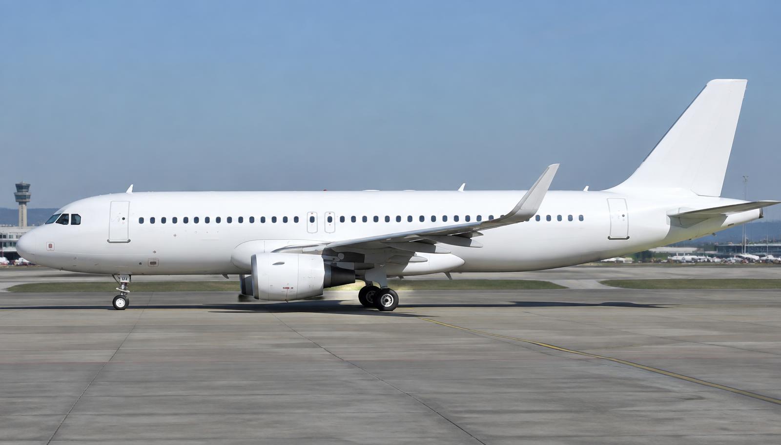
Where it is
Hydraulic System (Green / Blue / Yellow)
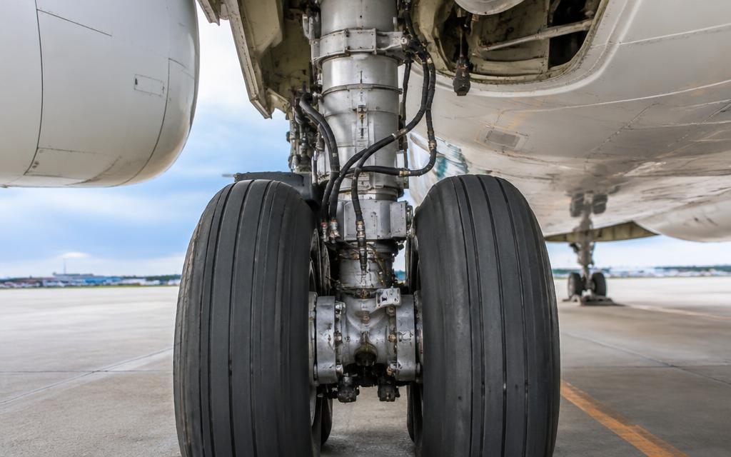
What it looks like
Controls
Engine 1
Engine 2
Yellow ELEC PUMP
PTU
RAT
Inject failures
What this means
- All three systems pressurised.
How it works
- Three independent systems — Green, Blue, Yellow — each at 3,000 psi with its own reservoir.
- Green is powered by an engine 1 pump; Yellow by an engine 2 pump and an electric pump; Blue by an electric pump.
- The PTU links Green and Yellow mechanically, so one can pressurise the other without mixing fluid.
- The RAT drops into the airflow in an emergency and drives a Blue pump.
How the parts work together
- Each flight control surface is powered by at least two systems, so losing one changes little.
- The PTU starts automatically if the pressure difference between Green and Yellow exceeds about 500 psi.
- Losing two systems puts the flight controls into alternate law and needs gear gravity extension.
What each part does
Click a box in the diagram or a part below to highlight it.
EDUCATIONAL USE ONLY. Content is summarised from manufacturer documentation for learning. It is not approved flight or maintenance data. Always use the current, aircraft-specific POH/AFM, FCOM, QRH, AMM and operator procedures.