Back to dashboard
Sections menu

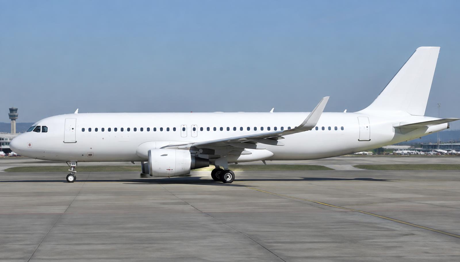
Airbus A320ceo / neo · Interactive FCOM

Full manual

Organised like the official Flight Crew Operating Manual with maintenance by ATA chapter. Search across every section.

Unverified — check your manualText on this page is written from general knowledge. Figures marked ✓ are checked against official FAA/EASA data.See verified data
1

General

EnginesCFM56-5B / IAE V2500 (ceo); LEAP-1A / PW1100G (neo)
MTOW78,000 kg (ceo typical)
Typical seats150–180
Range~3,300 nm (ceo) / 3,500 nm (neo)
MMOM 0.82
Ceiling39,100 ft (ceo) / 39,800 ft (neo)

Model applicability

  • A320ceo — CFM56-5B — 1988 – 2019 · S/N By MSN — see FCOM PLP / applicability
  • A320ceo — IAE V2500 — 1989 – 2019 · S/N By MSN
  • A320neo — LEAP-1A / PW1100G — 2016 – present · S/N By MSN
2

Limitations

Speeds

VMO / MMO✓ EASA350 kt / M 0.82
VLE — gear extended280 kt / M 0.67
VLO — extension / retraction250 / 220 kt
Max demonstrated crosswind (gust incl.)38 kt

Flight envelope

Max operating altitude✓ EASA39,100–39,800 ft (by model)
Load factor clean+2.5 / −1 g
Load factor slats/flaps extended+2 / 0 g

Engine (CFM56-5B, typical)

EGT start limit725 °C
EGT takeoff limit950 °C
Starter duty cycle3 cycles of 2 min, then 15 min cooling
3

Abnormal & Emergency Procedures

ENG FIRE (in flight)

Thrust lever (affected)IDLE
ENG MASTER (affected)OFF
ENG FIRE P/BPUSH
AGENT 1 (after 10 s)DISCH
ATCNOTIFY
If fire after 30 s: AGENT 2DISCH

ECAM procedure — follow actions as displayed. Source: FCOM PRO-ABN-26.

Emergency Descent

Crew oxygen masksUSE
SignsON
Emergency descentINITIATE
Thrust leversIDLE (if A/THR not engaged)
Speed brakeFULL
SpeedMAX / APPROPRIATE
ENG mode selIGN
ATCNOTIFY
Squawk 7700CONSIDER
Pax oxygen masksMAN ON (if cabin alt > 14,000 ft)

Dual Engine Failure (Fuel Remaining)

ENG MODE selIGN
Thrust leversIDLE
Optimum relight speed300 kt / M .77
EMER ELEC PWR (if RAT not ext)MAN ON
VHF1 / ATCUSE / NOTIFY
ENG MASTERSOFF 30 s, then ON (windmill relight)

Full procedure includes APU start below FL250 and ditching/forced landing preparation.

Rejected Takeoff

Thrust leversIDLE (CAPT calls 'STOP')
ReverseMAX
Braking (autobrake MAX)MONITOR / APPLY
Aircraft stoppedPARKING BRAKE ON
ATC & cabinNOTIFY ('Attention crew at stations')
EvacuationASSESS
4

Normal Procedures

Expanded, step-by-step versions with explanations: open the interactive procedures →

APU Start (amplified)

  1. 1. BAT 1 & 2 — CHECK > 25.5 V, then AUTO
    APU starter is powered from the batteries when no external power is connected.
  2. 2. APU MASTER SW — ON
    Opens the APU air intake flap and powers the ECB (APU computer).
  3. 3. APU START — ON
    Starter engages once the intake flap is open; START pb shows ON (blue).
  4. 4. APU page on SD — MONITOR N, EGT
    Watch EGT stays below limit; at ~95% N + 2 s, AVAIL illuminates.
  5. 5. APU AVAIL — CHECK
    APU generator can now supply the aircraft electrical network.
  6. 6. APU BLEED — ON
    Supplies air for packs and engine start.

Engine Start (Automatic) (amplified)

  1. 1. BEACON — ON
    Mandatory before engine start.
  2. 2. Thrust levers — IDLE
    FADEC will not start with levers out of idle.
  3. 3. Parking brake — CHECK ON / pressure
    Brake accumulator pressure holds the aircraft during start.
  4. 4. ENG MODE selector — IGN/START
    Arms the FADECs and displays the ENG page on SD. Packs close automatically during start.
  5. 5. ENG MASTER 2 — ON
    Starts the automatic sequence: start valve opens, N2 rises.
  6. 6. Start sequence — MONITOR
    Start valve opens → N2 rises → ignition and fuel at ~16–22% N2 → EGT rise → start valve closes ~50% N2.
  7. 7. Engine parameters — STABILISED at idle
    Check N1, N2, EGT, FF stable and oil pressure normal.
  8. 8. ENG MASTER 1 — ON
    Repeat sequence for engine 1.
  9. 9. ENG MODE selector — NORM
    Returns packs to normal; ignition becomes automatic only when required.
  10. 10. APU BLEED — OFF
    Engine bleed now supplies the packs.

After Landing & Parking (amplified)

  1. 1. Ground spoilers / Flaps — DISARM / RETRACT
    Configures for taxi.
  2. 2. APU — START
    Needed for power and air after engine shutdown.
  3. 3. Parking brake — ON
    Before shutting down engines.
  4. 4. ENG MASTER 1 & 2 — OFF
    Cuts fuel; FADEC controls the shutdown.
  5. 5. BEACON — OFF (when engines spooled down)
    Signals ground crew it's safe to approach.
  6. 6. FUEL PUMPS — OFF
    No engine demand; prevents unnecessary running.

Takeoff (FLEX) (amplified)

  1. 1. Takeoff data — CHECK — V1, VR, V2, FLEX temp entered in MCDU PERF
    Thrust and speeds must match the performance calculation.
  2. 2. Thrust levers — 50% N1 then FLX/MCT (or TOGA)
    Allowing engines to stabilise prevents asymmetric spool-up.
  3. 3. FMA — ANNOUNCE — MAN FLX xx, SRS, RWY, A/THR blue
    Confirms the automation modes that will fly the takeoff.
  4. 4. Sidestick — HALF FORWARD until 80 kt, then neutral
    Improves nosewheel steering effectiveness in crosswind.
  5. 5. Callouts — 100 kt, V1, ROTATE
    Crew cross-check.
  6. 6. Rotation — SMOOTH to approx. 15° pitch (follow SRS)
    Rotation rate approx. 3°/s avoids tail strike.
  7. 7. Positive climb — GEAR UP
    Reduces drag.
  8. 8. Thrust reduction altitude — Thrust levers — CL detent
    LVR CLB flashes on FMA; A/THR becomes active.
  9. 9. Flaps — RETRACT on schedule (F speed, S speed)
    Clean up at the green-dot speeds shown on the PFD.

ILS Approach & Landing (amplified)

  1. 1. Approach phase — ACTIVATE (decel point)
    Speed target becomes approach speeds.
  2. 2. APPR pushbutton — PRESS — check LOC/GS blue
    Arms localiser and glideslope capture.
  3. 3. Second autopilot — ENGAGE (for CAT II/III)
    Dual autopilot for autoland.
  4. 4. Flaps — 1 → 2 → GEAR DOWN → 3 → FULL
    Configure at F/S speeds.
  5. 5. Ground spoilers — ARM
    Automatic spoilers on touchdown.
  6. 6. Stabilised — BY 1,000 ft (IMC)
    On speed, on path, configured — otherwise go around.
  7. 7. Thrust levers — IDLE at 'RETARD' callout
    A/THR disconnects on idle.
  8. 8. Reversers — REV MAX or IDLE
    Then idle reverse by 70 kt.
  9. 9. Brakes — AUTOBRAKE / MANUAL
    Disconnect autobrake before 20 kt by pedals.

Engine Failure at or after V1 (amplified)

  1. 1. Rotation — NORMAL at VR, pitch approx. 12.5°
    Follow SRS — it targets V2 on one engine.
  2. 2. Rudder — CENTRE BETA TARGET (blue)
    The sideslip indicator turns blue as a beta target; centre it for best climb.
  3. 3. Positive climb — GEAR UP
    Drag reduction is vital on one engine.
  4. 4. Autopilot — ENGAGE when appropriate
    Reduces workload.
  5. 5. ECAM — ACTIONS above 400 ft AGL
    No actions below 400 ft except gear.
  6. 6. Engine-out acceleration altitude — PUSH ALT / level off, accelerate
    Clean up at green-dot.
  7. 7. Thrust levers — MCT at green dot
    Maximum continuous thrust for single-engine climb.

Emergency Descent (amplified)

  1. 1. Crew oxygen masks — ON
    Time of useful consciousness at FL350 is less than a minute.
  2. 2. Altitude — SET target, PULL
    Open descent.
  3. 3. Heading — PULL — turn off airway if required
    Avoid traffic.
  4. 4. Speed — MAX / APPROPRIATE
    Fastest descent unless structural damage.
  5. 5. Speed brake — FULL
    Increases descent rate.
  6. 6. ENG mode / signs — IGN if required, PAX OXY MASKS MAN ON if cabin > 14,000 ft
    Ensure passenger masks.
  7. 7. ATC / transponder — NOTIFY / 7700
    Clear traffic.

Cockpit Preparation (amplified)

  1. 1. Overhead panel scan — ALL WHITE LIGHTS OFF (except as required)
    The 'dark cockpit' philosophy: no lights = normal.
  2. 2. ADIRS — NAV (all three)
    Alignment takes about 10 minutes; don't move the aircraft.
  3. 3. FMGS — INIT, F-PLN, RAD NAV, PERF
    Flight plan and performance data.
  4. 4. FCU — SET initial altitude, FD ON
    Matches clearance.
  5. 5. ECAM — STATUS / RECALL checked
    Discover any deferred faults.
  6. 6. Parking brake / brake pressure — CHECK
    Accumulator pressure.

FMGS Initialisation & Route Entry (amplified)

  1. 1. DATA page — CHECK database validity
    Navigation database must be current (AIRAC).
  2. 2. INIT A — FROM/TO, flight number, CRZ FL, CI
    Sets departure/destination and cost index.
  3. 3. IRS align — CHECK position, ALIGN IRS
    IRs need correct position for alignment.
  4. 4. F-PLN — Lat REV at departure → SID & runway
    Departure procedure.
  5. 5. Airways / waypoints — Lat REV → AIRWAYS VIA / TO, insert
    Builds the en-route part.
  6. 6. Discontinuities — CLEAR
    A gap breaks managed NAV.
  7. 7. Arrival — Lat REV at destination → STAR / approach
    Expected arrival.
  8. 8. F-PLN check — COMPARE with OFP: fixes, distances, constraints
    Cross-check by both pilots.
  9. 9. RAD NAV — CHECK / SET navaids
    Auto-tuning normally fine.
  10. 10. INIT B (fuel) & PERF TO — ZFW, ZFWCG, block fuel; V1, VR, V2, FLEX, flaps
    Performance from load sheet and takeoff calculation.

Autopilot & Autothrust (FCU) (amplified)

  1. 1. AP 1 (or 2) — PUSH (above 100 ft after takeoff)
    Engages autopilot; check AP1 on FMA.
  2. 2. FMA — READ & CALL
    Five columns: thrust, vertical, lateral, approach, engagement status.
  3. 3. HDG knob — PUSH = managed NAV, PULL = selected HDG
    Push follows the FMS route; pull uses the knob value.
  4. 4. ALT knob — SET new level, PULL (OP CLB/DES) or PUSH (CLB/DES)
    Pull = open climb ignores constraints; push = managed respects them.
  5. 5. SPD knob — PUSH = managed, PULL = selected
    Speed from FMS or from the knob.
  6. 6. V/S knob — PULL and turn for a rate
    Vertical speed mode.
  7. 7. Thrust levers — CL detent
    A/THR active in CL; SPEED / THR CLB on FMA.
  8. 8. APPR / LOC — PUSH on approach, then second AP
    Arms ILS capture; both APs for autoland.
  9. 9. AP disconnect — Red button on sidestick
    Instinctive disconnect.

Cruise Fuel Check (amplified)

  1. 1. FOB on E/WD — READ
    Fuel on board from tank gauges.
  2. 2. MCDU F-PLN / FUEL PRED — CHECK EFOB at destination
    Predicted fuel at destination vs planned minimum.
  3. 3. SD FUEL page — CHECK balance & used
    FOB + fuel used should equal departure fuel — a gap suggests a leak.
  4. 4. Wind and temperature — UPDATE if different
    Keeps predictions realistic.
  5. 5. Cruise level / speed — Adjust if fuel is short
    Cost index and level affect burn.

Go-Around (amplified)

  1. 1. Thrust levers — TOGA
    Engages SRS and GA TRK; MAN TOGA on FMA.
  2. 2. Rotate — Follow SRS (approx. 15° pitch)
    Flight director gives go-around pitch.
  3. 3. Flaps — Retract ONE step
    e.g. FULL → 3: reduces drag while keeping lift.
  4. 4. Positive climb — CALL & gear UP
    Removes gear drag.
  5. 5. NAV / HDG — Engage as required
    Follow the missed approach.
  6. 6. At thrust reduction altitude — CL
    LVR CLB flashing — set climb thrust.

Engine Fire (in flight) (amplified)

  1. 1. THR LEVER (affected) — IDLE
    Confirm before moving — avoid shutting down the good engine.
  2. 2. ENG MASTER (affected) — OFF
    Stops fuel at HP and LP valves.
  3. 3. ENG FIRE P/B — PUSH
    Closes fuel, hydraulics, bleed and arms agents.
  4. 4. AGENT 1 — DISCH after 10 s
    Allows fan to run down so agent is not blown away.
  5. 5. ATC — NOTIFY (MAYDAY)
    Priority handling.
  6. 6. AGENT 2 — DISCH if fire after 30 s
    Second bottle.

Parking & Securing (amplified)

  1. 1. PARK BRK — ON (check pressure)
    Hold the aircraft before shutting down.
  2. 2. ENG MASTERS — OFF
    Shut down engines.
  3. 3. BEACON — OFF
    Signals ground staff it's safe to approach.
  4. 4. FUEL PUMPS — OFF
    Not needed with engines off.
  5. 5. APU BLEED — OFF before securing
    Before APU shutdown.
  6. 6. ADIRS — OFF (when securing)
    Shut down the IRs.

Exterior Walkaround — Nose

Probes & sensors (pitot, static, AOA)CONDITION, covers removed
RadomeCONDITION, latches
Nose gear & tiresCONDITION, no leaks
Nosewheel steering pinAS REQUIRED
Avionics compartment doorCLOSED

Right / Left Wing & Engines

Fan blades, exhaustCONDITION
Engine cowlingsCLOSED & LATCHED
Slats, flaps, aileronsCONDITION
Wing tip & lightsCONDITION
Fuel vent / NACA intakeCLEAR
Main gear, brakes, wear pinsCHECK
TiresCONDITION

Tail & Fuselage

Stabilizer, elevator, rudderCONDITION
APU air intake & exhaustCLEAR
Outflow valveCONDITION
Cargo doorsCHECK
Static dischargersCHECK

Cockpit Preparation

BatteriesCHECK (>25.5 V)
External power / APUON
ADIRSNAV
Overhead panelALL WHITE LIGHTS OFF
Fuel quantityCHECK
MCDU (INIT, F-PLN, PERF)COMPLETE
OxygenTEST

Before Start

Cockpit prepCOMPLETED
Gear pins & coversREMOVED
SignsON / AUTO
ADIRSNAV
Fuel quantity___ KG
TO dataSET
Baro refSET (both)
Windows / doorsCLOSED
BeaconON
Thrust leversIDLE
Parking brakeAS RQRD

Takeoff

Thrust leversFLX or TOGA
FMACHECK & ANNOUNCE
100 ktCHECK
V1HAND OFF THRUST LEVERS
VRROTATE (~3°/s)
Positive climbGEAR UP
Thrust reduction altCL detent
F speed / S speedFLAPS 1 / FLAPS 0

Before Landing

Cabin crewADVISED
AutothrustSPEED / OFF
ECAM memoLDG NO BLUE (gear dn, signs on, spoilers armed, flaps set)
5

Performance

Airline performance is computed with the operator's approved performance software (e.g. Airbus FlySmart / Boeing OPT) — not tabulated here.

7

Airplane & Systems Description

Glass Cockpit & Fly-by-Wire ATA 22, 23, 31, 34, 35

Where it is

Location of Glass Cockpit & Fly-by-Wire
Glass Cockpit & Fly-by-Wire

Sidestick controllers, six display units (ECAM + EFIS), and electronic flight control laws.

  • Sidestick inputs go to flight control computers (2 ELACs, 3 SECs, 2 FACs) which command the surfaces — no mechanical link except rudder and stabilizer trim backup.
  • Normal Law provides protections: high angle of attack, load factor (+2.5 g / −1 g clean), pitch attitude, bank angle and high speed.
  • Degraded laws: Alternate Law and Direct Law, with Mechanical Backup as last resort.
  • ECAM (Electronic Centralised Aircraft Monitor) displays system pages and automatically presents failure procedures.
  • FMGS: two FMGCs handle navigation, performance and autopilot / autothrust.

High-Bypass Turbofans ATA 26, 36, 71, 72, 73, 74, 78, 79

Where it is

Location of High-Bypass Turbofans
High-Bypass Turbofans

What it looks like

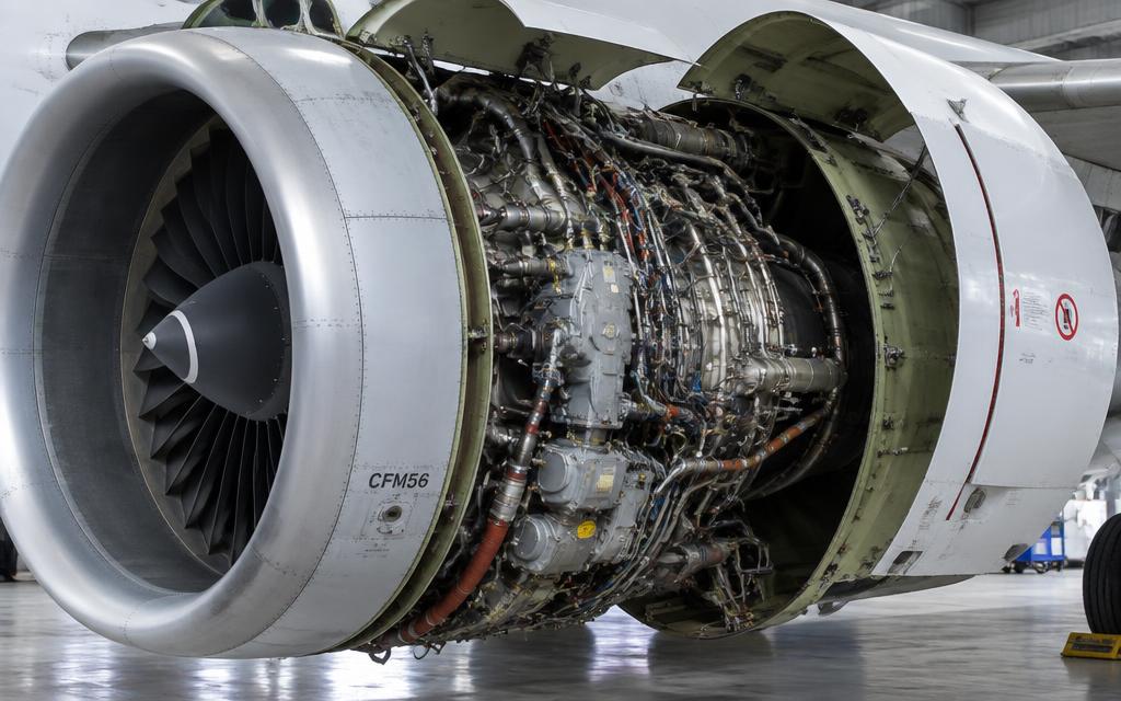
CFM56 with fan cowls open — accessory gearbox, pipes and harnesses
CFM56 with fan cowls open — accessory gearbox, pipes and harnesses · illustrative image

Two wing-mounted turbofans controlled by FADEC with thrust lever detents (CL, FLX/MCT, TOGA).

  • FADEC (Full Authority Digital Engine Control) manages fuel flow, start sequence, and protections for each engine.
  • Autothrust: thrust levers set in CL detent; A/THR commands thrust between idle and CL.
  • Each engine drives a hydraulic pump (Green: ENG 1, Yellow: ENG 2) and an IDG generator (90 kVA).
  • Bleed air from the HP/IP compressor supplies pressurization, air conditioning and wing anti-ice.
  • Fire detection by dual loops; two extinguisher bottles per engine.

Wings & Flight Controls ATA 27, 28, 30, 57

Where it is

Location of Wings & Flight Controls
Wings & Flight Controls

What it looks like

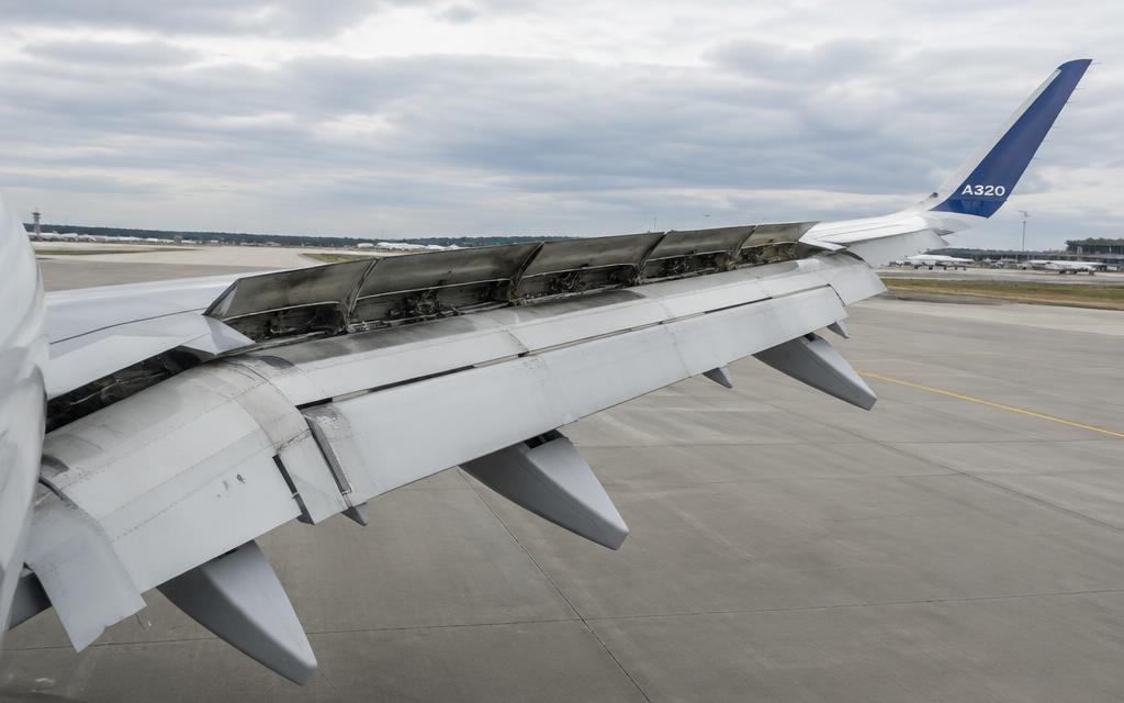
Wing with spoilers, flaps and flap-track fairings
Wing with spoilers, flaps and flap-track fairings · illustrative image

Supercritical wing with slats, Fowler flaps, five spoilers per wing, ailerons, and wingtip fences or sharklets.

  • Slats and flaps are commanded via the FLAPS lever (0, 1, 2, 3, FULL) through SFCCs; driven by hydraulic motors through torque shafts.
  • Roll is controlled by ailerons plus spoilers 2–5; all spoilers act as ground spoilers, 2–4 as speed brakes.
  • Wing tanks plus a center tank; fuel pumps feed engines with crossfeed valve available.
  • Wing anti-ice uses engine bleed air on three outboard slats.

Retractable Landing Gear ATA 29, 32

Where it is

Location of Retractable Landing Gear
Retractable Landing Gear

What it looks like

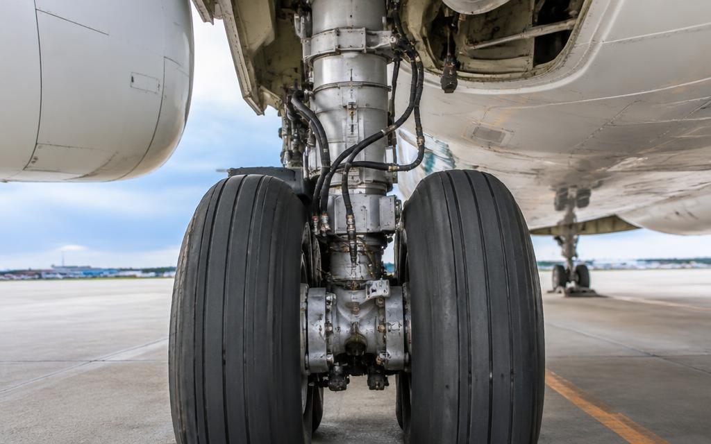
Main gear — twin wheels, carbon brakes, oleo strut and hydraulic lines
Main gear — twin wheels, carbon brakes, oleo strut and hydraulic lines · illustrative image

Hydraulically operated tricycle gear (Green system) with autobrake and anti-skid.

  • Gear is controlled by two LGCIUs; extension/retraction via Green hydraulic system.
  • Gravity extension by handcrank in the cockpit if hydraulics fail.
  • Carbon brakes with normal (Green) and alternate (Yellow + accumulator) braking; BSCU manages anti-skid and autobrake (LO / MED / MAX).
  • Nosewheel steering ±75° via tiller, ±6° via rudder pedals.

Fuselage, Pressurization & Air ATA 21, 24, 25, 52, 53

Where it is

Location of Fuselage, Pressurization & Air
Fuselage, Pressurization & Air

Wide single-aisle cabin (3.70 m external width) with two air-conditioning packs and digital pressurization.

  • Two packs cool and condition bleed air, mixed with recirculated cabin air in the mixer unit.
  • Two Cabin Pressure Controllers drive an outflow valve; max differential pressure 8.6 psi.
  • Electrical: 115 V AC and 28 V DC; RAT deploys automatically if AC BUS 1 & 2 lost above 100 kt, powering the emergency generator via Blue hydraulics.
  • Cargo holds forward and aft, with smoke detection.

Empennage & APU ATA 49, 55

Where it is

Location of Empennage & APU
Empennage & APU

What it looks like

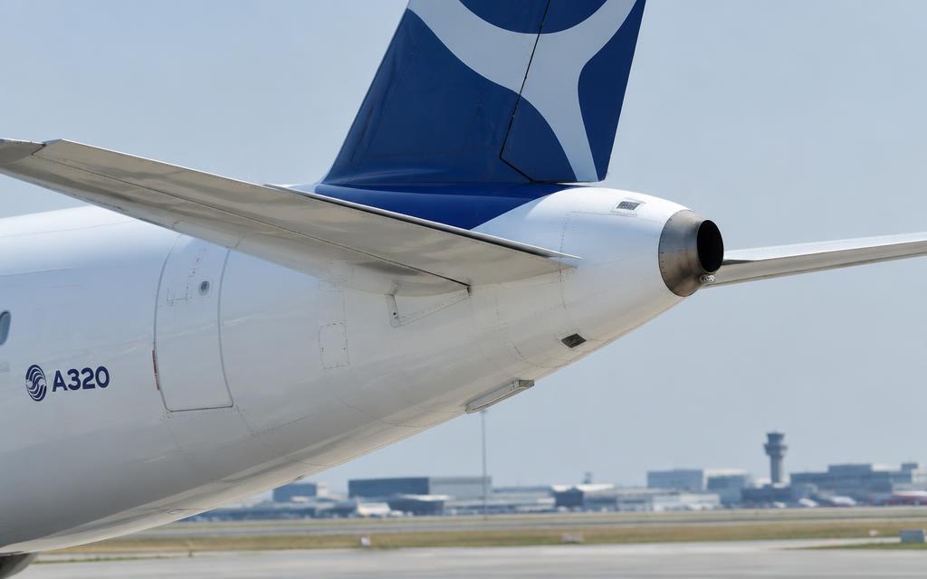
Tail cone with APU exhaust, rudder and horizontal stabilizer
Tail cone with APU exhaust, rudder and horizontal stabilizer · illustrative image

Trimmable horizontal stabilizer, elevators, rudder, and APU in the tail cone.

  • Pitch trim is automatic in Normal Law via the trimmable horizontal stabilizer (THS); mechanical trim wheel as backup.
  • Rudder controlled by pedals with yaw damping from FACs; mechanical link retained.
  • APU (Honeywell 131-9A or APIC APS3200) supplies bleed air and 90 kVA electrical power on ground and in flight.
7A

Annunciators & Fault Messages

Open the interactive fault finder →

ENG 1(2) OIL LO PREngine oil pressure below the red line.
HYD G SYS LO PRGreen system pressure low.
ELEC GEN 1(2) FAULTA generator's control unit has tripped it offline.
AIR ENG 1(2) BLEED FAULTBleed overheat, overpressure or leak — bleed valve closes.
CAB PR EXCESS CAB ALTCabin altitude above 9,550 ft.
FUEL L(R) TK PUMP 1(2) LO PROne wing tank pump output low; the other pump in that tank continues to feed.
ENG 1(2) FIREFire detected in the engine nacelle by both loops (or one if the other is faulty). Red FIRE pushbutton and ENG master FIRE light illuminate, continuous repetitive chime.
HYD G+Y SYS LO PRGreen and yellow systems lost. Only blue remains. Alternate law, no autopilot, gear by gravity, reduced spoilers, no NWS, alternate braking via accumulator only.
ELEC EMER CONFIGAC BUS 1 and 2 lost. RAT extends, emergency generator powers the essential network. Captain's displays only, one FMGC, alternate law.
Unreliable airspeedSpeed or altitude indications erroneous (blocked pitot / static, icing, ADR fault). May cause wrong protections and warnings.
ENG 1(2) FAIL / SHUT DOWNEngine failure (flameout, damage). Autothrust and rudder trim compensate in normal law; FMGS provides single-engine data.
FUEL IMBALANCEDifference between wing tank quantities exceeds limits. Check for a leak before correcting.
AVIONICS SMOKE / SMOKESmoke detected in the avionics ventilation duct or cabin/cargo.
BRAKES HOTA brake temperature above 300 °C. Fire risk and possible tyre fusible plug release.
ENG 1(2) STALLCompressor stall: bangs, vibration, EGT rise, N1/N2 fluctuation.
CAB PR SYS 1+2 FAULTBoth cabin pressure controllers failed; automatic control lost.
F/CTL ALTN LAWFly-by-wire degraded to alternate law: most protections lost, pitch still load-factor demand, roll direct.
L/G GEAR NOT DOWNBelow 750 ft RA in landing configuration with gear not down and locked. Red warning, continuous chime.
TCAS RA — CLIMB / DESCENDTraffic collision avoidance resolution advisory. Follow the green area on the vertical speed scale.
WINDSHEAR (reactive)Red WINDSHEAR on PFD with aural 'WINDSHEAR' x3 — energy loss detected during takeoff or approach.
7B

Systems In Depth (engine, gear, controls…)

Deep dive · ATA 21

Air Conditioning & Pressurisation — in depth

Packs

Two air conditioning packs in the belly fairing take hot bleed air (about 200 °C) via the pack flow control valves. Each pack is an air-cycle machine: primary heat exchanger, compressor, main heat exchanger, turbine (expansion cools the air well below 0 °C) and water extractor.

Pack outlet air goes to the mixer unit where it mixes with recirculated cabin air (filtered). Hot trim air is added per zone (cockpit, fwd cabin, aft cabin) to reach the selected temperature, controlled by the zone controller and two pack controllers.

Packs2 air-cycle machines
ZonesCockpit, FWD cabin, AFT cabin
Temperature selection18–30 °C
Pack flow selectorLO / NORM / HI
RecirculationApprox. 40–50 % of cabin airflow through HEPA filters

Pressurisation control

Two Cabin Pressure Controllers (CPC) operate automatically, one active and one standby, swapping each flight. They modulate the single outflow valve in the aft fuselage, using the FMGS landing elevation and QNH data to schedule cabin altitude.

Two safety valves open at about 8.6 psi positive differential, and also prevent negative differential greater than about −1 psi.

Max differential8.6 psi (safety valve)
Normal max cabin altitudeapprox. 8 000 ft
Cabin altitude warning9 550 ft (+/−350)
DitchingCloses outflow valve, inlet and extract valves

Pressurisation failures

CAB PR SYS 1 FAULTAutomatic transfer to system 2 — no action
CAB PR SYS 1+2 FAULTMODE SEL to MAN; control V/S with MAN V/S CTL toggle
CAB PR EXCESS CAB ALTMasks on, descent per ECAM (emergency descent if required)
LDG ELEV FAULTSet landing elevation manually

Warning · Excessive cabin altitude: crew oxygen masks on and establish communication first — time of useful consciousness at FL350 is only about 30–60 seconds.

Deep dive · ATA 22

Auto Flight — FMGS in depth

Components

Two Flight Management and Guidance Computers (FMGC), each with a flight management part (navigation, flight planning, performance prediction) and a flight guidance part (autopilot, flight director, auto-thrust). Two MCDUs, one FCU (Flight Control Unit) with two independent channels, and two FACs (flight augmentation computers: yaw damper, rudder trim/limit, characteristic speeds).

Managed vs selected guidance

Managed (dot shown in the FCU window, knob pushed): the FMGS computes targets from the flight plan. Selected (knob pulled): the pilot's FCU value is the target. The FMA on the PFD always shows what is engaged (green) and armed (blue).

Lateral modesNAV, HDG, TRK, LOC, RWY, GA TRK
Vertical modesCLB, DES, OP CLB, OP DES, ALT, ALT CST, V/S, FPA, G/S, SRS
A/THR modesSPEED, MACH, THR CLB, THR IDLE, THR MCT, TOGA
AutolandCAT IIIB with both APs (LAND, FLARE, ROLL OUT)

Deep dive · ATA 24

Electrical Power — AC/DC network in depth

Generation

Normal AC sources: two IDGs (one per engine, 90 kVA, 115/200 V, 400 Hz, three-phase), one APU generator (90 kVA) and external power. In emergency, the RAT drives a 5 kVA emergency generator (CSM/G) via the blue hydraulic system. Batteries (2 × 23 Ah, 24 V) supply the DC battery buses and, via a static inverter, the AC essential bus when nothing else is available.

DC power comes from three Transformer Rectifiers (TR 1, TR 2, ESS TR) converting 115 V AC to 28 V DC.

IDG output90 kVA, 115/200 V, 400 Hz
APU GEN90 kVA
Emergency generator5 kVA (RAT driven)
Batteries2 × 24 V, 23 Ah
TRs3 × 200 A
Static inverter1 kVA, AC ESS SHED supply on batteries only

Distribution priority

AC BUS 1 is normally fed by GEN 1, AC BUS 2 by GEN 2. Priority for each bus: on-side engine generator, then external power, then APU generator, then opposite engine generator (through the bus tie contactors). Only one source can feed a bus at a time — sources are never paralleled.

AC ESS BUS is normally fed from AC BUS 1 (switchable to AC BUS 2 with AC ESS FEED). DC ESS is fed by DC BUS 1 via DC BAT BUS, or by the ESS TR in emergency.

In the emergency electrical configuration (loss of both AC main buses above 100 kt), the RAT extends automatically, the emergency generator powers AC ESS and (via ESS TR) DC ESS. On batteries alone, about 30 minutes of essential power remains.

Key ECAM procedures

ELEC IDG 1 OIL LO PR / OVHTIDG disconnect (guarded) — irreversible in flight; reset only on ground with engine stopped
ELEC GEN 1 FAULTGEN 1 OFF then ON; APU GEN to replace if available
ELEC EMER CONFIGLand ASAP; RAT out; restore generators per ECAM; limited systems
ELEC BAT 1 (2) FAULTBattery contactor open — check charge current and temp

Warning · IDG disconnection cannot be reconnected in flight. Never press the IDG button unless the ECAM procedure calls for it.

Maintenance

IDG oil level is checked through a sight glass (green/yellow band) after shutdown; servicing uses a pressure-fill kit and the oil is replaced on condition with filter Δp indication. Battery capacity checks per MPD; TR load tests via CFDS (Centralised Fault Display System) BITE.

Deep dive · ATA 26

Fire Protection — in depth

Detection

Each engine and the APU have two identical detection loops (A and B) mounted in parallel, each a gas-filled sensing element connected to a responder. Heat expands the gas and closes a pressure switch; the Fire Detection Unit (FDU) triggers the warning only when both loops detect (AND logic). If one loop is faulty, the other alone can trigger the warning.

Cargo holds and lavatories have smoke detectors (optical) monitored by the Smoke Detection Control Unit; the avionics bay has a smoke detector too.

Extinguishing

Each engine has two Halon fire bottles (squibs fired by the AGENT pushbuttons). The APU has one bottle. The forward and aft cargo holds on many A320s have one or two bottles shared between them (option dependent).

Pushing the ENG FIRE pushbutton (guarded, red) silences the aural warning, arms the squibs and closes the LP fuel valve, hydraulic fire-shutoff valve, engine bleed and pack flow valve, and de-energises the IDG.

Engine bottles2 per engine
APU bottle1, auto-discharge on ground
Lav waste binAutomatic extinguisher (heat fused)
AgentHalon 1301 (CF3Br)

Engine fire procedure (in flight, outline)

  1. 1.Thrust lever (affected engine) IDLE.
  2. 2.ENG MASTER OFF.
  3. 3.ENG FIRE pushbutton PUSH.
  4. 4.AGENT 1 DISCH after 10 s countdown (ECAM shows the timer).
  5. 5.ATC notify.
  6. 6.If fire persists after 30 s: AGENT 2 DISCH.

Warning · Teaching outline only — follow the approved ECAM/QRH.

Maintenance

Fire bottle pressure gauge vs temperature chart; squib resistance and continuity BITE via CFDS; loop tests (FIRE TEST pb) daily/preflight; hydrostatic test of bottles at defined years; detector loop clamps inspected for chafing.

Deep dive · ATA 27

Fly-by-wire — in depth

Computers

ELAC × 2Elevator Aileron Computers — normal pitch and roll
SEC × 3Spoiler Elevator Computers — spoilers, standby elevator and stabilizer
FAC × 2Flight Augmentation Computers — rudder, yaw damper, flight envelope speeds
SFCC × 2Slat Flap Control Computers

Control laws

Normal Law: the sidestick commands a load factor (pitch) and a roll rate. Protections: high angle of attack (alpha floor, alpha max), load factor (+2.5 g / –1 g clean), pitch attitude (+30°/–15°), bank angle (67°), high speed.

Alternate Law: after multiple failures — pitch still load-factor demand but most protections lost (replaced by stability). Direct Law: sidestick deflection directly moves surfaces, as in a conventional aircraft; 'USE MAN PITCH TRIM' displays.

Mechanical backup: rudder via cables and pitch trim via the stabilizer trim wheel — keeps the aircraft controllable while computers are reset.

Deep dive · ATA 28

Fuel System — in depth

Tanks

Each wing has an inner tank and an outer tank; there is a centre tank in the wing-box and (optionally) Additional Centre Tanks (ACT) in the cargo hold. Outer tanks drain into the inner tanks through transfer valves when inner tank quantity drops to about 750 kg; the fuel is kept outboard as long as possible for wing bending relief.

Each inner tank contains two electric booster pumps; the centre tank has two pumps. A cross-feed valve allows either side to feed both engines.

Total usable (no ACT)approx. 24 000 L / approx. 19 000 kg
Outer tank (each)approx. 690 kg
Inner tank (each)approx. 5 500 kg
Centre tankapprox. 6 500 kg
Fuel typesJet A, Jet A-1, JP-8 (others per AFM)

Feeding logic

  1. 1.Centre tank pumps run at a higher output pressure than wing pumps, so centre fuel is used first when centre pumps are ON.
  2. 2.On the A320ceo with the auto mode, centre pumps run when slats are retracted and stop when the centre tank is empty (5 min after LO LVL) — wing pumps then feed.
  3. 3.Inner tanks feed until about 750 kg, when outer-tank transfer valves open; outer fuel flows by gravity into the inner tanks.
  4. 4.Fuel also recirculates through the IDG coolers back to the outer tanks (fuel is used as a heat sink for IDG oil).

Imbalance & leaks

Lateral imbalance limits are in the FCOM limitations. If imbalance develops, first check for a fuel leak (compare FOB + FU with departure fuel, check individual tank trends, look at the engine) before cross-feeding. Feeding from the low side into a leaking engine accelerates the loss.

Warning · Do not open the cross-feed if a leak from an engine or pylon is suspected.

Maintenance

Water drainsTank sump drains daily / per MPD (cold soak condensation)
Fuel quantityCapacitance probes + FQIC; manual magnetic level indicators (MLI) under the wing
Tank entryRequires full venting, gas-free test, standby person, confined-space permit

Deep dive · ATA 29

Hydraulics — in depth

Three independent systems

GreenEngine-1-driven pump (EDP). Gear, normal brakes, reverser 1, flight controls
BlueElectric pump + Ram Air Turbine (RAT). Flight controls, emergency generator
YellowEngine-2-driven pump + electric pump + hand pump (cargo doors). Alternate brakes, steering, reverser 2
Pressure3000 psi nominal (2500 psi with RAT)
FluidPhosphate-ester (Skydrol / Hyjet)

Power Transfer Unit (PTU)

A reversible hydraulic motor-pump linking green and yellow without mixing fluid. It runs automatically when the pressure difference between the two exceeds about 500 psi. Its characteristic 'barking dog' sound is heard on the ground when one engine is started.

Warning · Skydrol is very irritating to eyes and skin — always wear goggles and gloves when servicing.

Ram Air Turbine

Drops out automatically if both AC buses are lost above 100 kt, or manually. It drives a blue hydraulic pump, which in turn drives the constant-speed motor/generator (CSM/G) for emergency electrics.

Deep dive · ATA 30

Ice & Rain Protection — in depth

Systems

Wing anti-ice: hot bleed air to the three outer leading-edge slats on each wing. Engine anti-ice: separate bleed from each engine to the nacelle lip. Electric heating: pitot, static ports, AOA probes, TAT probes, windshields (and side windows), drain masts. Rain removal by wipers and (option) rain repellent.

WING ANTI ICE on groundValves open 30 s test only
Probe heatAutomatic with one engine running; PROBE/WINDOW HEAT pb ON for manual

Deep dive · ATA 32

Landing Gear — in depth

Configuration

Retractable tricycle gear with twin wheels on each leg. Mains retract inward into the wing-root/fuselage bays; the nose gear retracts forward. Each leg has an oleo-pneumatic shock absorber (nitrogen over oil).

Gear and doors are operated by the green hydraulic system. Two Landing Gear Control and Interface Units (LGCIU 1 and 2) receive proximity-sensor signals and alternate control on each retraction cycle.

Main tyres46 × 17R20 (typical), approx. 200 psi
Nose tyres30 × 8.8R15, approx. 180 psi
Max gear-extended speed VLE280 kt / M 0.67
Max extension VLO250 kt
Max retraction VLO220 kt
Max tyre speed195 kt groundspeed

Normal extension & retraction

  1. 1.Lever DOWN: the LGCIU commands the selector valve, the gear doors open, uplocks release, the gear extends by gravity and actuators and the downlock struts lock.
  2. 2.Doors close again once the gear is locked down (main doors). Three green triangles appear on the LDG GEAR indicator and ECAM WHEEL page.
  3. 3.Lever UP: hydraulic pressure is cut above 260 kt via a safety valve; wheels are braked automatically during retraction to stop them spinning in the bay.

Gravity (free-fall) extension

Turning the gravity extension crank 3 turns clockwise isolates the gear hydraulics, unlocks the doors and gear uplocks mechanically. The gear falls by gravity and aerodynamic drag; the downlock springs lock it. Doors stay open.

Braking

Normal brakesGreen hydraulic, controlled by BSCU with anti-skid
Alternate brakesYellow hydraulic, through the ALTN brake valve; anti-skid if BSCU available
AccumulatorYellow — at least 7 full brake applications or parking brake for 12 h
AutobrakeLO (decel 1.7 m/s² after 4 s), MED (3 m/s² after 2 s), MAX (RTO only)
Brake temp limit for takeoff300 °C (fans off) / 150 °C with fans

Nosewheel steering

Yellow hydraulic, controlled by the BSCU from the tillers (±75°) and rudder pedals (±6°, faded out with speed above 40 kt, none above 130 kt). The A/SKID & N/W STRG switch turns both off. For towing, a steering disconnect pin removes hydraulic steering so the tug can turn up to ±95°.

Warning · Exceeding the towing angle limit can shear the steering components — always check the red marks on the nose gear.

Deep dive · ATA 34

Navigation & Avionics — ADIRS, displays and radio navigation

ADIRS

Three Air Data Inertial Reference Units (ADIRU 1, 2, 3). Each contains an Air Data Reference part (ADR: airspeed, altitude, Mach, AOA, temperature from pitot, static and AOA probes via Air Data Modules) and an Inertial Reference part (IR: ring-laser gyros and accelerometers for attitude, heading, position, ground speed).

Alignment takes about 10 minutes on the ground (longer at high latitudes). The aircraft must not be moved during alignment. ADIRU 3 can replace 1 or 2 via the switching panel (ATT HDG / AIR DATA selector).

ADIRUs3
Alignment timeapprox. 10 min (up to ~17 min at high latitude)
IR drift (typical)< 2 NM/h
Probes3 pitot, 6 static, 3 AOA, 2 TAT

EFIS / ECAM

Six identical display units: PFD and ND per pilot, E/WD (engine / warning) and SD (system display). Driven by three Display Management Computers (DMC). If a DMC fails, the EIS DMC switching selector transfers to DMC 3. A failed PFD transfers automatically to the ND position; a failed E/WD to the SD.

Radio navigation

Two VOR/DME, two ILS (MMR — multi-mode receivers with GPS/GLS), ADF (optional), two radio altimeters, weather radar, TCAS and transponders. Radio nav tuning is automatic through the FMGC, with manual backup via RMP (radio management panels).

Deep dive · ATA 36

Pneumatic — bleed air in depth

Engine bleed

Air is taken from the HP compressor intermediate stage (IP, stage 5) and, at low engine power, from stage 9 (HP) through the HP valve. The pressure-regulating valve (bleed valve) regulates to about 45 psi; a precooler cooled by fan air limits temperature to about 200 °C.

Two Bleed Monitoring Computers (BMC) monitor pressure/temperature and leaks; leak detection loops along the ducts trigger AIR ENG BLEED LEAK and close the affected valve.

Regulated pressureapprox. 45 psi
Precooler outlet tempapprox. 200 °C
UsersPacks, wing anti-ice, engine start, hydraulic reservoir pressurisation, water tank

Deep dive · ATA 49

APU — in depth

Construction

Honeywell 131-9A or APIC APS 3200 single-shaft gas turbine in the tail cone, behind a firewall. Load compressor supplies bleed air; the gearbox drives the 90 kVA generator and fuel/oil pumps. An ECB (Electronic Control Box) controls start, speed (100 %) and protective shutdowns.

Max start altitude (batt)approx. 25 000 ft
Bleed use up toapprox. 20 000–22 500 ft
Electrical use up toMax certified altitude
Speed100 % governed
Cooldown after bleed useapprox. 60–120 s automatic

Start sequence

  1. 1.MASTER SW ON: ECB powers up, air intake flap opens, fuel pump runs (if no tank pressure).
  2. 2.START pb ON: at flap fully open, starter engages.
  3. 3.At about 7 % ignition and fuel on; at about 55 % starter cuts out.
  4. 4.At 95 % + 2 s (or 99.5 %) AVAIL shows; bleed and electrical load can be taken.

Auto shutdowns

Fire (on ground)Auto shutdown + bottle discharge
Overspeed / underspeedShutdown
Low oil pressure / high oil tempShutdown
EGT overtempShutdown
Inlet flap closedShutdown

Deep dive · ATA 72

Engines — CFM56-5B / IAE V2500 / LEAP-1A / PW1100G

Engine architecture (CFM56-5B as example)

Two-spool, high-bypass turbofan. The low-pressure (N1) spool is the fan, a 4-stage booster and a 4-stage low-pressure turbine on one shaft. The high-pressure (N2) spool is a 9-stage HP compressor driven by a single-stage HP turbine.

About 5.5–6 times more air goes around the core (bypass) than through it. Most of the thrust comes from the fan, not from the hot exhaust.

The annular combustor has 20 fuel nozzles. Two igniters (A and B) are fitted; one is used on each ground start and both in flight starts and in continuous ignition.

Thrust22,000–33,000 lbf depending on rating
Bypass ratioapprox. 5.5–6 : 1 (LEAP-1A approx. 11 : 1)
Fan diameter68.3 in (CFM56-5B)
Overall pressure ratioapprox. 32 : 1
N1 max104 %
N2 max105 %
EGT max takeoff950 °C
EGT max start725 °C

FADEC — Full Authority Digital Engine Control

Each engine has a two-channel Engine Control Unit (ECU, or EEC on the V2500) mounted on the fan case. It has full authority over fuel flow, variable stator vanes, bleed valves, clearance control and ignition. There is no mechanical link from the thrust lever.

The ECU is powered by its own dedicated alternator on the gearbox once N2 is above about 12%; before that, aircraft power is used. The channel in control swaps on each engine start.

It protects against overspeed and over-temperature, and during automatic start it aborts the start on hot start, hung start, no light-off or stall, and attempts a re-crank.

Automatic start sequence

  1. 1.ENG MODE selector to IGN/START: pack valves close (if APU bleed), ECAM shows the ENGINE page.
  2. 2.ENG MASTER 1 ON: the start valve opens, pneumatic starter turns the N2 spool — air from the APU or the other engine.
  3. 3.At about 16% N2: ignition A or B on. At about 22% N2: HP fuel valve opens and fuel flows.
  4. 4.Light-off: EGT rises within about 15 seconds of fuel.
  5. 5.At about 50% N2: start valve closes, igniter off. Engine stabilises at idle (about 58% N2, about 19% N1).

Warning · In MANUAL start the FADEC only protects during the start of the engine on the ground — the crew must watch EGT and abort if it approaches the limit.

Thrust lever detents & autothrust

TOGAMaximum takeoff / go-around thrust
FLX/MCTFlexible (reduced) takeoff thrust using assumed temperature, or Max Continuous
CLClimb — autothrust active range is between IDLE and CL
IDLEIdle thrust
REV IDLE / MAX REVThrust reverser deployed

Oil system

Dry-sump, pressurised system. The oil tank is on the fan case; a gearbox-driven lubrication pump feeds the bearing sumps, and scavenge pumps return oil through a fuel-cooled oil cooler (servo fuel heater) to the tank. Magnetic chip detectors in each scavenge line catch metal particles from bearing wear.

Min oil quantity before dispatchapprox. 9.5 qt + estimated consumption (varies by engine)
Oil pressure lowRed below approx. 13 psi
Max oil temp155 °C continuous

Thrust reversers

Fan-air (cascade) reverser: translating sleeves slide aft, blocker doors close the bypass duct and fan air is turned forward through cascade vanes. Hydraulically actuated — engine 1 from green, engine 2 from yellow. Interlocks require weight on wheels and the FADEC signal; the reverser can only be selected with thrust levers at idle.

8A

Maintenance Task Cards

Pressurisation & outflow valve operational test

ATA 21 · Per MPD

Access · Flight deck; external access to outflow valve

Tools & materials · CFDS / MCDU · Ground power

Warning · Keep hands clear of the outflow valve doors during test.

  1. 1.Run the CPC BITE from the MCDU via CFDS and check no faults recorded.
  2. 2.Select MODE SEL MAN; operate MAN V/S CTL up and down; observe the outflow valve moving on the SD CAB PRESS page and visually.
  3. 3.Return MODE SEL to AUTO; confirm the valve moves to its auto position.
  4. 4.Inspect the valve doors for damage and seals for wear.
Valve travelFully open to fully closed, smooth

Ref: A320 AMM 21-31-00

IDG oil level check & servicing

ATA 24 · Weekly / per MPD

Access · Engine fan cowl opened

Tools & materials · IDG servicing kit (pressure fill) · Approved oil (MIL-PRF-23699) · Lint-free cloth

Warning · Fan cowl opening in wind > limit is prohibited — secure the hold-open rods.

  1. 1.Engine shut down at least 5 min (IDG oil must settle; hot oil overfills reading).
  2. 2.Open the fan cowls and read the IDG sight glass: green band = OK, yellow = overfill, below = service.
  3. 3.To service: connect fill hose to the fill valve, overflow hose to the overflow drain; pump oil until it flows out the overflow, then stop.
  4. 4.Disconnect, cap, check for leaks, close cowls.
Oil typeMIL-PRF-23699 / approved list
Differential pressure indicatorReplace filter if popped

Ref: A320 AMM 24-21-00

Engine fire bottle pressure check

ATA 26 · Per MPD (weekly / A-check)

Access · Pylon access panels

Tools & materials · Pressure/temperature chart · Thermometer

Warning · Squibs are explosive devices — fit shorting plugs and follow ESD precautions.

  1. 1.Read the bottle pressure gauge.
  2. 2.Measure ambient temperature and compare with the pressure-temperature chart.
  3. 3.Check the discharge indicator disc is intact.
  4. 4.Check the squib connectors and safety cap.
Nominal pressure @ 21 °Capprox. 600 psi (per chart)

Ref: A320 AMM 26-21-00

Fuel tank water drain

ATA 28 · Daily / per MPD

Access · Under the wing

Tools & materials · Drain tool · Clear container · Water detection paste/capsules

  1. 1.After the fuel has settled (min 2 h preferred), open each sump drain valve with the tool.
  2. 2.Collect fuel until it runs clear; test with water detection capsules.
  3. 3.Close the valve, check it does not leak.
  4. 4.Record the result in the technical log.
Free waterNone allowed after draining

Ref: A320 AMM 12-13-28

Hydraulic reservoir servicing

ATA 29 · As required

Access · Ground service panel (green/blue/yellow)

Tools & materials · Hand pump with filter · Phosphate-ester fluid

Warning · Wear eye protection; Skydrol damages paint and wiring insulation.

  1. 1.Depressurise systems; reservoir must be at normal (not pressurised) status.
  2. 2.Read reservoir level against the 'refill' scale corrected for the accumulator pressure.
  3. 3.Connect the hand pump to the selected reservoir fill coupling via the selector valve.
  4. 4.Pump to the NORMAL FILL line.
  5. 5.Disconnect and fit caps.
Green reservoirapprox. 14 L
Blue reservoirapprox. 6 L
Yellow reservoirapprox. 12 L

Ref: AMM 12-12-29

Main gear tyre pressure check

ATA 32 · Daily

Access · Gear accessible on ground

Tools & materials · Calibrated tyre gauge · Nitrogen cart

Warning · Stand at the side, never in front of the wheel — a failed wheel can explode outward.

  1. 1.Check cold tyres only (at least 3 h after flight, or compensate).
  2. 2.Compare reading with the placard pressure for the aircraft weight.
  3. 3.Inflate with dry nitrogen only.
  4. 4.If 5–10 % below: inflate and record; recheck in 24 h. >10 %: remove tyre (and the companion on the same axle if it rolled under-inflated).
Loss allowed per 24 h5 %
Hot tyre pressureup to +10 % above cold

Ref: AMM 12-14-32

Brake wear pin check

ATA 32 · Daily / weekly check

Access · Visual at wheel

Tools & materials · Torch · Ruler

  1. 1.Parking brake ON (pressurises the brake).
  2. 2.Measure the exposed length of each wear indicator pin.
  3. 3.If the pin is flush with or below the housing face, schedule brake replacement.
Wear pinmust protrude from the housing (min 0 mm)

Ref: AMM 32-42-27

APU oil level check

ATA 49 · Daily / per MPD

Access · APU access doors, tail cone

Tools & materials · Approved oil · Gravity fill or pressure fill kit

  1. 1.APU shut down at least 5 min (or within limits per AMM).
  2. 2.Open the APU access doors and read the sight glass, or use the ECAM APU page low-oil-level indication.
  3. 3.Service through the gravity fill port to FULL.
  4. 4.Close doors and record.
OilMIL-PRF-23699

Ref: A320 AMM 12-13-49

Engine oil servicing (CFM56-5B)

ATA 79 · Daily / as required

Access · Fan cowl oil service door

Tools & materials · Approved oil (e.g. Mobil Jet Oil II) · Gravity fill can or pressure servicing cart

Warning · Engine oil is toxic; avoid skin contact. Hot oil may spray if the cap is removed too early.

  1. 1.Wait 5–60 min after shutdown — oil level reads correctly only in that window.
  2. 2.Open the oil service access door; check level on the sight gauge.
  3. 3.Remove filler cap slowly (tank may be pressurised).
  4. 4.Fill to the FULL mark. Do not overfill.
  5. 5.Reinstall cap and check it is locked. Close the door.
  6. 6.Record quantity added for oil consumption monitoring.
Max oil consumptionapprox. 0.4 qt/h (trend monitored)

Ref: AMM 12-13-79

8

Maintenance Overview (by ATA)

ATA 21 — Air Conditioning & Pressurization

  • Inspect door seals and slide bottle pressures per AMM 25/52.
  • Pack heat exchanger cleaning per MPD; outflow valve inspection.
  • Structural inspections per Airworthiness Limitations (ALS) and Corrosion Prevention & Control Programme.

ATA 22 — Auto Flight

  • Flight control computer BITE tests via CFDS/MCDU per AMM Chapter 27.
  • ADIRU alignment and air data checks; pitot-static leak tests per AMM 34.
  • Display unit and ECAM software configuration verified against approved standard.

ATA 23 — Communications

  • Flight control computer BITE tests via CFDS/MCDU per AMM Chapter 27.
  • ADIRU alignment and air data checks; pitot-static leak tests per AMM 34.
  • Display unit and ECAM software configuration verified against approved standard.

ATA 24 — Electrical Power

  • Inspect door seals and slide bottle pressures per AMM 25/52.
  • Pack heat exchanger cleaning per MPD; outflow valve inspection.
  • Structural inspections per Airworthiness Limitations (ALS) and Corrosion Prevention & Control Programme.

ATA 25 — Equipment / Furnishings

  • Inspect door seals and slide bottle pressures per AMM 25/52.
  • Pack heat exchanger cleaning per MPD; outflow valve inspection.
  • Structural inspections per Airworthiness Limitations (ALS) and Corrosion Prevention & Control Programme.

ATA 26 — Fire Protection

  • Engine oil uplift checked each transit/daily check; consumption trend monitored.
  • Borescope inspections of HPT/combustor per engine manufacturer's ESM and MPD.
  • Fan blade visual inspection for FOD damage at each walkaround; lubrication of fan blade roots at shop visits.
  • Fire detection loop and bottle squib tests per AMM 26.

ATA 27 — Flight Controls

  • Slat/flap track lubrication and inspection per MPD intervals.
  • Inspect leading edges and sharklets for bird strike or lightning damage at walkaround.
  • Fuel tank water drain and sampling per operator's schedule.

ATA 28 — Fuel

  • Slat/flap track lubrication and inspection per MPD intervals.
  • Inspect leading edges and sharklets for bird strike or lightning damage at walkaround.
  • Fuel tank water drain and sampling per operator's schedule.

ATA 29 — Hydraulic Power

  • Check tire pressure daily; inspect tires and brake wear indicators at each walkaround.
  • Shock absorber servicing (nitrogen/oil) per AMM 32.
  • Gear retraction tests and lubrication per MPD.

ATA 30 — Ice & Rain Protection

  • Slat/flap track lubrication and inspection per MPD intervals.
  • Inspect leading edges and sharklets for bird strike or lightning damage at walkaround.
  • Fuel tank water drain and sampling per operator's schedule.

ATA 31 — Indicating / Recording

  • Flight control computer BITE tests via CFDS/MCDU per AMM Chapter 27.
  • ADIRU alignment and air data checks; pitot-static leak tests per AMM 34.
  • Display unit and ECAM software configuration verified against approved standard.

ATA 32 — Landing Gear

  • Check tire pressure daily; inspect tires and brake wear indicators at each walkaround.
  • Shock absorber servicing (nitrogen/oil) per AMM 32.
  • Gear retraction tests and lubrication per MPD.

ATA 34 — Navigation

  • Flight control computer BITE tests via CFDS/MCDU per AMM Chapter 27.
  • ADIRU alignment and air data checks; pitot-static leak tests per AMM 34.
  • Display unit and ECAM software configuration verified against approved standard.

ATA 35 — Oxygen

  • Flight control computer BITE tests via CFDS/MCDU per AMM Chapter 27.
  • ADIRU alignment and air data checks; pitot-static leak tests per AMM 34.
  • Display unit and ECAM software configuration verified against approved standard.

ATA 36 — Pneumatic

  • Engine oil uplift checked each transit/daily check; consumption trend monitored.
  • Borescope inspections of HPT/combustor per engine manufacturer's ESM and MPD.
  • Fan blade visual inspection for FOD damage at each walkaround; lubrication of fan blade roots at shop visits.
  • Fire detection loop and bottle squib tests per AMM 26.

ATA 49 — Airborne Auxiliary Power (APU)

  • APU oil level check daily; APU fire detection test.
  • THS actuator ballscrew lubrication and inspection per MPD.
  • Static dischargers on control surfaces inspected at walkaround.

ATA 52 — Doors

  • Inspect door seals and slide bottle pressures per AMM 25/52.
  • Pack heat exchanger cleaning per MPD; outflow valve inspection.
  • Structural inspections per Airworthiness Limitations (ALS) and Corrosion Prevention & Control Programme.

ATA 53 — Fuselage

  • Inspect door seals and slide bottle pressures per AMM 25/52.
  • Pack heat exchanger cleaning per MPD; outflow valve inspection.
  • Structural inspections per Airworthiness Limitations (ALS) and Corrosion Prevention & Control Programme.

ATA 55 — Stabilizers

  • APU oil level check daily; APU fire detection test.
  • THS actuator ballscrew lubrication and inspection per MPD.
  • Static dischargers on control surfaces inspected at walkaround.

ATA 57 — Wings

  • Slat/flap track lubrication and inspection per MPD intervals.
  • Inspect leading edges and sharklets for bird strike or lightning damage at walkaround.
  • Fuel tank water drain and sampling per operator's schedule.

ATA 71 — Power Plant

  • Engine oil uplift checked each transit/daily check; consumption trend monitored.
  • Borescope inspections of HPT/combustor per engine manufacturer's ESM and MPD.
  • Fan blade visual inspection for FOD damage at each walkaround; lubrication of fan blade roots at shop visits.
  • Fire detection loop and bottle squib tests per AMM 26.

ATA 72 — Engine

  • Engine oil uplift checked each transit/daily check; consumption trend monitored.
  • Borescope inspections of HPT/combustor per engine manufacturer's ESM and MPD.
  • Fan blade visual inspection for FOD damage at each walkaround; lubrication of fan blade roots at shop visits.
  • Fire detection loop and bottle squib tests per AMM 26.

ATA 73 — Engine Fuel & Control

  • Engine oil uplift checked each transit/daily check; consumption trend monitored.
  • Borescope inspections of HPT/combustor per engine manufacturer's ESM and MPD.
  • Fan blade visual inspection for FOD damage at each walkaround; lubrication of fan blade roots at shop visits.
  • Fire detection loop and bottle squib tests per AMM 26.

ATA 74 — Ignition

  • Engine oil uplift checked each transit/daily check; consumption trend monitored.
  • Borescope inspections of HPT/combustor per engine manufacturer's ESM and MPD.
  • Fan blade visual inspection for FOD damage at each walkaround; lubrication of fan blade roots at shop visits.
  • Fire detection loop and bottle squib tests per AMM 26.

ATA 78 — Exhaust / Thrust Reverser

  • Engine oil uplift checked each transit/daily check; consumption trend monitored.
  • Borescope inspections of HPT/combustor per engine manufacturer's ESM and MPD.
  • Fan blade visual inspection for FOD damage at each walkaround; lubrication of fan blade roots at shop visits.
  • Fire detection loop and bottle squib tests per AMM 26.

ATA 79 — Oil

  • Engine oil uplift checked each transit/daily check; consumption trend monitored.
  • Borescope inspections of HPT/combustor per engine manufacturer's ESM and MPD.
  • Fan blade visual inspection for FOD damage at each walkaround; lubrication of fan blade roots at shop visits.
  • Fire detection loop and bottle squib tests per AMM 26.

EDUCATIONAL USE ONLY. Content is summarised from manufacturer documentation for learning. It is not approved flight or maintenance data. Always use the current, aircraft-specific POH/AFM, FCOM, QRH, AMM and operator procedures.