ATA 21
Air Conditioning & Heating
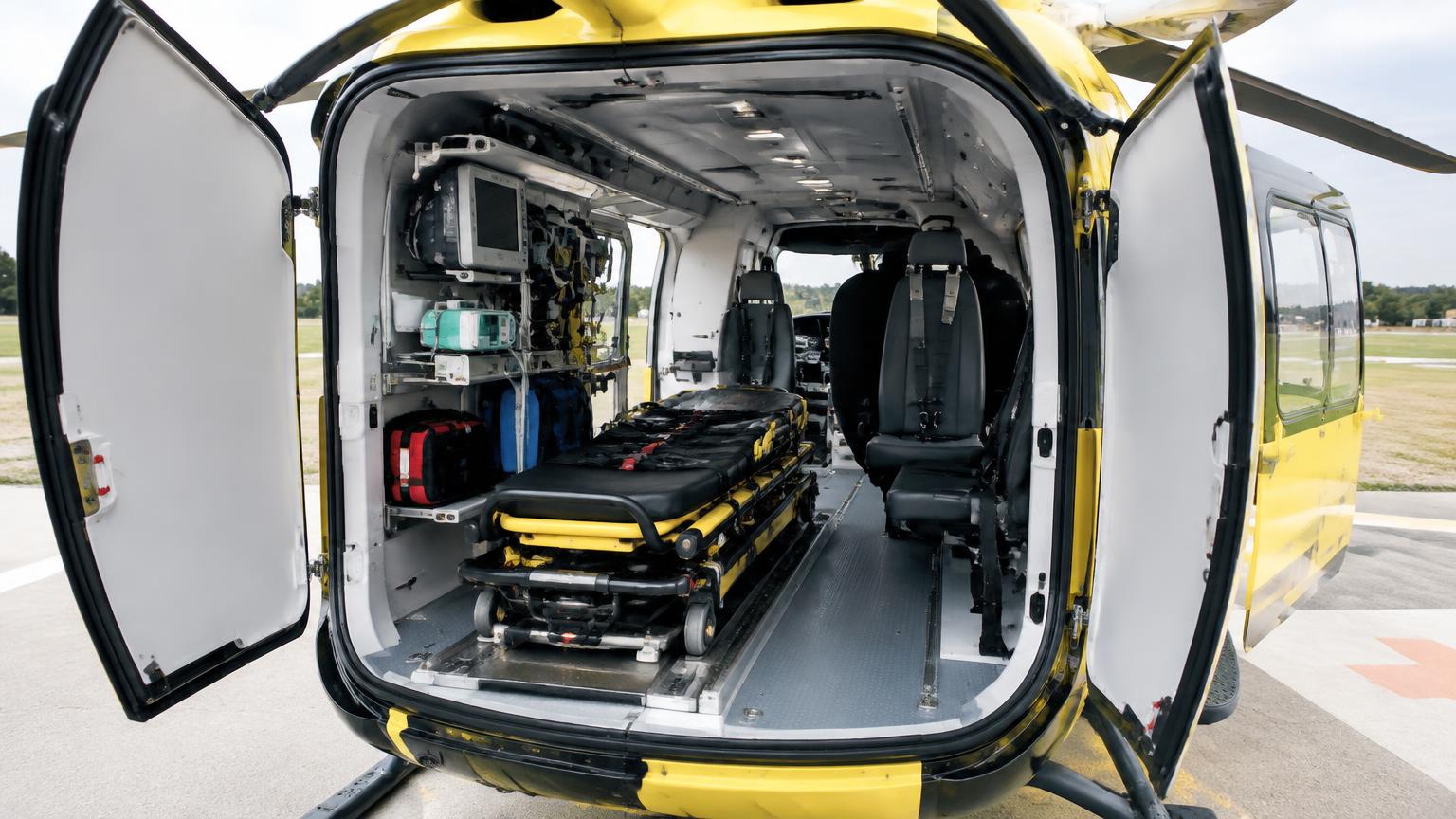
The H145 is unpressurised, so ATA 21 covers only cabin/cockpit heating, ventilation and windshield demisting — there is no cabin pressurisation, outflow valve or air-cycle pack as on fixed-wing jets. Bleed air tapped from each Arriel 2E engine (or an independent combustion heater on some fit-outs) feeds a mixer that blends hot air with fresh ram/fan air, distributed through cockpit and cabin ducts and floor/overhead outlets. Fresh-air vents and eyeball outlets supplement airflow, and electric blower fans assist circulation on the ground when rotors are not generating ram air. HEMS-configured aircraft often add a separate cabin heater/air conditioning unit for patient comfort, run from the electrical system.
Where it is
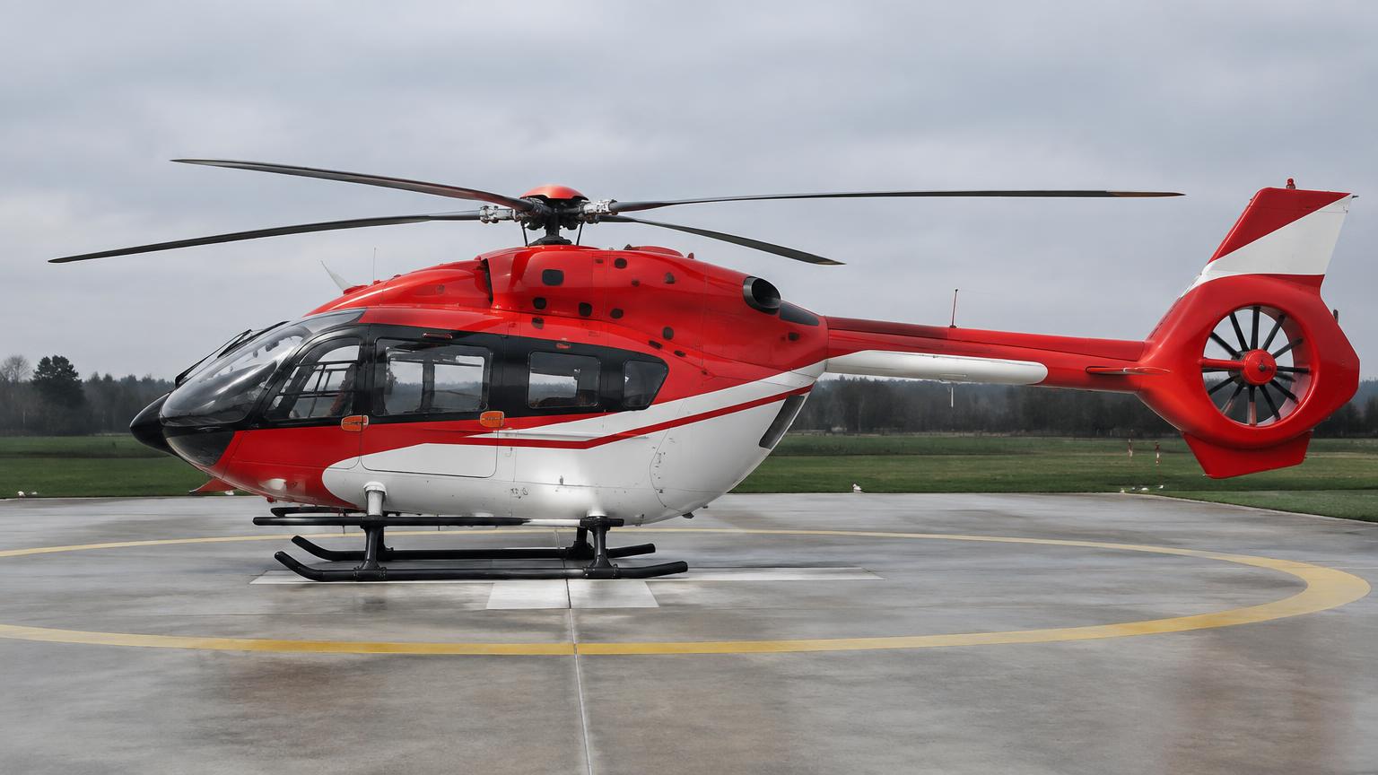
What it looks like
Technical data
| Item | Value |
|---|---|
| Pressurisation | None — unpressurised cabin |
| Heat source | Engine bleed air and/or independent fuel-fired cabin heater |
| Cockpit demist | Hot air ducted to windshield outlets |
| Cabin A/C (optional) | Electrically driven vapour-cycle unit, HEMS/VIP fit |
| Ventilation fans | Electric, for ground/low-speed cooling |
Components
1.Bleed air valve
Taps regulated bleed air from each engine for the heating mix manifold.
A pneumatic valve on each Arriel 2E that taps regulated compressor bleed air for the H145's heating/demist mix manifold. One valve per engine, mounted on the engine casing near the compressor bleed port.
- FADEC-scheduled or thermostatically modulated bleed flow is routed through stainless steel lines to a mixer valve; the valve throttles flow as a function of selected cabin temperature and bleed pressure available from the engine, closing automatically at low NG to protect engine performance during critical phases.
| Bleed pressure | approx. 3-5 bar at cruise NG |
| Bleed temperature | approx. 150-200 C |
| Valve type | electro-pneumatic, spring-loaded closed |
- Valve sticks open: Cabin overheat, possible engine performance loss, crew selects heat OFF
- Valve fails closed: No cabin heat available, demist function lost
- Inspect for bleed air leaks/soot staining at fittings
- Functional check of valve response during ground run
- Check wiring/connector condition if electrically actuated
2.Mixer/distribution valve
Blends hot bleed air with fresh air to the selected temperature.
A single mixing valve downstream of the two engine bleed taps that blends hot bleed air with ambient fresh air before it enters the cockpit/cabin duct network of the H145.
- A rotary or butterfly element proportions hot and cold air streams based on the temperature selector position; a temperature sensor in the mix duct feeds back to the control logic (manual or automatic) to hold the selected outlet temperature, with crew able to override to full cold or full hot.
| Mix outlet temp range | approx. ambient to 60-70 C |
| Control | manual rheostat or automatic thermostat |
- Valve jams mid-position: Uneven or uncontrollable cabin temperature
- Sensor failure: Mix defaults to a fail-safe position, usually full cold
- Verify full range of travel on ground test
- Check linkage/cable rigging for binding
- Inspect sensor wiring continuity
3.Cockpit and cabin ducts
Flexible ducting to floor and console outlets and windshield demist nozzles.
Flexible, lightweight ducting that carries conditioned air from the mixer valve to floor-level and console outlets and to windshield demist nozzles throughout the H145 cockpit and cabin.
- Low-pressure air flows by a combination of engine bleed differential pressure and the electric blower, through corrugated hose runs clipped along the airframe structure to individual outlet fittings; duct routing avoids chafing against wiring and flight control runs per design.
| Duct material | silicone/fiberglass flexible hose |
| Operating pressure | near-ambient, low differential |
- Duct chafe/leak: Reduced flow to downstream outlets, localized hot spot
- Duct detachment: Loss of demist or cabin heat at affected outlet
- Inspect duct clamps and routing for chafe against structure/wiring
- Check for crushed or kinked sections on removal of panels
- Verify outlet airflow during ground test
4.Eyeball fresh-air vents
Adjustable outlets for crew and passengers/patients.
Individually adjustable swivel outlets at each crew and passenger/patient position in the H145 cabin, allowing local control of fresh air direction and flow.
- Each vent is a ball-and-socket diffuser fed from the main distribution duct; a rotating collar or lever opens/closes an internal shutter to vary flow independent of the central temperature selection, giving occupants individual comfort control.
| Flow control | manual rotary shutter, 0-100% |
| Supply source | blower-boosted fresh air duct |
- Vent shutter seized: Fixed airflow, cannot be closed or opened by occupant
- Vent detached from mount: Air loss to intended duct run, draft elsewhere
- Check for free rotation and shutter operation
- Inspect mounting ring for cracking
- Confirm airflow present at each vent during system test
5.Electric blower fan
Circulates cabin air on the ground or at low rotor downwash.
A DC electric fan unit in the H145 air distribution system that boosts cabin airflow on the ground or when rotor downwash and ram air are insufficient, such as during hover or ground idle.
- Powered from the DC bus, the fan draws fresh air through an inlet scoop/filter and pushes it into the mix/distribution ducting; it runs continuously at low power settings or is thermostatically/manually switched, independent of engine bleed air operation.
| Supply voltage | 28V DC |
| Typical current draw | a few amps |
- Fan motor failure: Reduced airflow especially on ground/hover, crew relies on ram air in flight
- Bearing wear/noise: Audible vibration, eventual seizure
- Listen for abnormal bearing noise during ops check
- Inspect inlet screen for debris/blockage
- Check circuit breaker and wiring for condition
6.Cabin heater (combustion type, optional)
Independent fuel-burning heater for HEMS cabins, with overheat protection.
An independent, fuel-burning combustion heater fitted to HEMS-configured H145s to provide cabin heat without relying on engine bleed air, typically mounted in a baggage/equipment bay.
- The unit draws fuel from the aircraft fuel system, burns it in a sealed combustion chamber with its own air supply and exhaust, and transfers heat to cabin air via a heat exchanger; overheat and flame-out sensors shut the unit down automatically, with a cockpit switch for crew control and a smoke/fire warning tie-in.
| Fuel source | aircraft Jet A/Jet A-1 supply |
| Overheat protection | automatic shutdown thermostat/sensor |
- Overheat trip: Heater shuts down, cabin heat lost, possible smoke/fire caution
- Ignition failure: No heat output, fault light/CAS message
- Inspect combustion chamber and exhaust for soot/cracking
- Test overheat sensor function per maintenance schedule
- Check fuel line fittings for leaks
7.Air conditioning unit (optional)
Electrically powered vapour-cycle cooling for cabin/patient comfort on VIP/HEMS kits.
An electrically powered vapour-cycle cooling system fitted to VIP and HEMS H145 cabins for patient/passenger thermal comfort, with the compressor and condenser typically mounted externally or in a dedicated bay.
- An electric compressor circulates refrigerant through condenser and evaporator coils in a standard vapour-cycle loop; cabin air is blown across the evaporator coil and ducted to cabin outlets, with the compressor cycling on thermostat demand and drawing significant DC or inverter-supplied AC power.
| Power source | 28V DC or inverter-derived AC |
| Refrigerant | HFC-type, e.g. R134a |
- Compressor failure: Loss of cooling, CAS caution, heater/vent fallback
- Refrigerant leak: Reduced cooling capacity, low-pressure switch may inhibit compressor
- Check refrigerant charge/pressure per schedule
- Inspect condenser coil for debris obstruction
- Verify compressor clutch/cycling operation on ground test
Operation
- The crew selects a temperature/flow with a rotary or push-button control; the mixer valve proportions hot bleed air against cold ambient air to hold that setting.
- Windshield demist is selected independently and takes priority for visibility in icing/fogging conditions.
- On HEMS aircraft the cabin heater or air conditioner is run from a separate panel by the medical crew, independent of cockpit controls, to keep the patient compartment at a set temperature.
- Ground cooling relies on the electric blower since there is no ram air until the rotor is turning and forward airspeed is present.
Controls
| Control | Function |
|---|---|
| CKPT TEMP / CABIN TEMP selector | Rotary or rocker on the overhead/console panel. |
| DEMIST switch | Directs hot air to windshield outlets. |
| Cabin heater/AC panel | Separate switch panel for HEMS/VIP cabin climate control. |
| Blower fan switch | Electric ventilation fan on/off. |
Indications
| Indication | Meaning |
|---|---|
| CAS/MFD caution | Bleed valve fault or heater overheat shown as a Helionix CAS message. |
| Duct temperature placard | No dedicated gauge in basic fit; pilot judges by feel and CAS alerts. |
Failures & crew actions
| Failure | Effect / action |
|---|---|
| Bleed valve stuck open/closed | Loss of temperature control; CAS message, select heater off and use fresh air vents. |
| Cabin heater overheat | Automatic shutdown and CAS caution; do not reset in flight, land and have it inspected. |
| Smoke/fumes from heater | Heater off, vents open, follow smoke/fumes emergency checklist. |
Maintenance
- Functional test of bleed/mixer valve and ducting for leaks at scheduled AMM intervals.
- Inspect combustion heater fuel lines, igniter and overheat switches per the fuel-fired heater's own maintenance manual.
- Check cabin blower fan brushes/bearings and duct attachment security.
- Leak-check bleed ducting in the engine deck area for hot-air chafe and clamp security.
Deep dive · ATA 21
Heating, Ventilation & Air Conditioning — in depth
Cabin heat & bleed air
Cabin and cockpit heat is supplied from engine bleed air (or an electric heater element on some utility fits) through a mixing valve that blends hot bleed air with ambient ram/fan air to the selected temperature. There is no pressurisation system — the cabin is unpressurised and bleed air use is only for heating, demisting and (on some fits) de-icing/de-misting of the windscreen.
An optional air conditioning (vapour-cycle) pack, often fitted for HEMS/VIP configurations, uses an electrically or belt-driven compressor and evaporator in the cabin headliner; it is a stand-alone system separate from the heating bleed-air circuit.
| Heat source | Engine bleed air (mixed with ambient) or electric element |
| Pressurisation | None — unpressurised cabin |
| Optional A/C | Vapour-cycle, electrically driven compressor |
| Windscreen demist | Hot air outlets at the lower windscreen |
Ventilation
Fresh-air ventilation comes from cockpit/cabin eyeball vents fed by ram air (and a blower at low airspeed/on the ground) plus openable cabin windows on utility doors. Cabin crew/medical configurations often add dedicated fans for equipment cooling and patient-compartment airflow.
Fumes & smoke
A bleed-air or electrical heat fault can introduce fumes or overheat smells into the cabin; the QRH drill is to select heat/bleed OFF, increase fresh-air ventilation, and land as soon as practicable if smoke persists.
Warning · Treat any unexplained smoke or fume odour from the heating system as an emergency — do not continue troubleshooting airborne beyond the checklist actions.
Educational summary — verify against the official AMM/FCOM/POH for your aircraft.