Back to dashboard
Sections menu

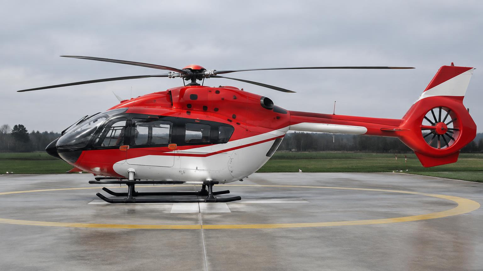
Airbus H145 (BK117 D-2) · Interactive FCOM

Full manual

Organised like the official Flight Crew Operating Manual with maintenance by ATA chapter. Search across every section.

Unverified — check your manualText on this page is written from general knowledge. Figures marked ✓ are checked against official FAA/EASA data.See verified data
1

General

Engines2 x Safran Arriel 2E turboshafts, dual-channel FADEC
MTOWapprox. 3,700 kg (D-2) / 3,800 kg (D-3)
Cruise speedapprox. 135 kt
Main rotor4-blade bearingless/hingeless (D-3: 5-blade)
Tail rotorFenestron shrouded fan
Landing gearSkids (wheeled ground handling gear optional)

Model applicability

  • BK117 C-2 / EC145 (predecessor) — 2000 - 2014 · S/N By MSN - see manufacturer applicability list
  • H145 D-2 (BK117 D-2) — 2014 - present · S/N By MSN - see RFM applicability
  • H145 D-3 (five-blade rotor) — 2019 - present · S/N By MSN - see RFM applicability
  • H145M / UH-72 Lakota (military) — 2014 - present · S/N Military serials; UH-72 per US Army contract
2

Limitations

Speeds (KIAS)

VNE — never exceed (sea level, typical)approx. 140-150 kt (altitude/weight dependent, see RFM chart)
VNE — autorotationLower than power-on VNE, see RFM chart
Max demonstrated crosswind (hover/landing)approx. 25-30 kt (RFM dependent)

Rotor & powerplant

Rotor RPM (NR) — power-on rangeapprox. 98-104% (RFM exact band)
Rotor RPM (NR) — autorotation rangeWider band, see RFM, with low-NR and high-NR cautions
OEI 30-second ratingImmediate one-engine-inoperative emergency power
OEI 2-minute ratingShort-term one-engine-inoperative power
OEI continuous ratingSustained one-engine-inoperative power
TOT / NG limitsPer FLI and Arriel 2E FADEC schedule

Weight & envelope

MTOW✓ EASAapprox. 3,700 kg (D-2) / 3,800 kg (D-3)
Load factor (typical utility category)approx. +3.0 / -0.5 g, see RFM
Max operating altitude (density altitude dependent)Performance-limited by OEI hover/climb charts, not a fixed ceiling figure
3

Abnormal & Emergency Procedures

Single-Engine Failure (OEI)

CollectiveADJUST to maintain NR / FLI within OEI limits
Failed engineIDENTIFY (FADEC / CAS message)
Failed engine FADEC/start leverAS PER RFM (idle or OFF)
OEI rating (30s/2min/continuous)APPLY AS REQUIRED, do not exceed time limits
AirspeedADJUST toward single-engine best rate of climb
LandAS SOON AS PRACTICABLE

The FADEC automatically provides OEI power from the remaining engine; monitor the FLI for the limiting parameter.

Dual-Engine Failure / Autorotation

CollectiveLOWER IMMEDIATELY to maintain NR
AttitudeADJUST for autorotative glide speed
Landing siteSELECT, into wind if possible
Fuel levers / FADECOFF when landing assured
Collective (flare and cushion)APPLY NEAR GROUND to arrest rate of descent
After touchdownCOLLECTIVE FULL DOWN, brakes as required

Rotor RPM control is the single most critical action — do not allow NR to decay.

Engine Fire (Ground or Flight)

Affected engine FADEC/start leverOFF
Fire extinguishing systemDISCHARGE (as installed)
Remaining engineMONITOR, apply OEI rating if required
CAS fire warningCONFIRM EXTINGUISHED
LandAS SOON AS POSSIBLE

Tail Rotor (Fenestron) Drive or Control Failure

Yaw tendencyIDENTIFY (loss of pedal authority vs drive failure)
AirspeedINCREASE to use vertical fin for weathercock stability
CollectiveREDUCE smoothly to reduce torque/yaw demand
ApproachRUN-ON LANDING preferred over hover if pedal authority is reduced
Engines (if complete drive failure)SHUT DOWN per RFM before touchdown as required

The shrouded Fenestron reduces but does not eliminate loss-of-tail-rotor-effectiveness risk; always follow the RFM tail rotor malfunction procedure for the actual failure mode.

4

Normal Procedures

Expanded, step-by-step versions with explanations: open the interactive procedures →

Preflight Walkaround (amplified)

  1. 1. General condition — WALK AROUND, nose to tail, both sides
    Catches skin damage, leaks and missing fasteners before they become inflight problems.
  2. 2. Main rotor blades & head — CHECK — leading edge, tip caps, dampers, pitch links
    The bearingless/hingeless main rotor (ATA 62) relies on the flexbeam and elastomeric bearings staying free of cracks and leaks.
  3. 3. Main gearbox (MGB) — CHECK oil level & no leaks
    The MGB (ATA 63) carries full torque from both engines and must show no chip light history or seepage.
  4. 4. Fenestron tail rotor & drive shaft — CHECK blades, shroud, couplings
    The shrouded Fenestron (ATA 64/65) is less exposed to strike damage than an open tail rotor, but couplings and the gearbox still need a visual and a feel check.
  5. 5. Engines & FADEC — CHECK cowlings secure, inlets clear, no leaks
    Each Arriel 2E has its own dual-channel FADEC (ATA 73/76); a blocked inlet or loose cowling is caught only by a close look.
  6. 6. Hydraulic reservoirs (SYS 1 & 2) — CHECK levels
    The two independent hydraulic systems boost the cyclic, collective and pedal servo-actuators (ATA 67) — low level is an early warning of a leak.
  7. 7. Skids / gear — CHECK condition, ground handling wheels stowed
    Skid gear has no retraction system to fail, but cracked cross tubes or worn skid shoes are a structural concern.
  8. 8. Static ports, pitot, OAT probe — CHECK clear and undamaged
    Feeds the Helionix air data computers — a blocked port gives unreliable airspeed on the PFD page.
  9. 9. Doors, cabin and baggage — CHECK secure, load within limits
    MTOW is approx. 3,700 kg (D-2); loading affects CG and the hover power margin.

Cockpit Preparation (amplified)

  1. 1. BAT switch — ON
    Powers the 28 VDC essential bus so the Helionix system can initialise before the engines run.
  2. 2. 3 MFDs — CHECK self-test, select ENGINE/SYSTEM page
    Confirms all three Helionix displays are alive; any display can show any page if one fails.
  3. 3. CAS messages — REVIEW and CLEAR as applicable
    The Crew Alerting System lists faults by colour (red warning, amber caution, white advisory) — know what's already present before you add engine-start messages.
  4. 4. FMS / Helionix flight plan — CHECK database, enter route if known
    Loads navigation data the Helionix 4-axis AFCS will later use for NAV mode.
  5. 5. Cyclic trim / force trim — CHECK release & re-engage
    Verifies the electric trim actuators that hold cyclic position are working before flight.
  6. 6. Collective friction & lever — CHECK full range, FULL DOWN with ECLs at OFF
    A collective that creeps will fight the engine start and hover checks.
  7. 7. HYD 1 & 2 switches — ON
    Pressurises the flight-control servo-actuators before the controls are checked.
  8. 8. Cyclic & pedals — FULL & FREE check
    Confirms no control restriction before the rotors turn.
  9. 9. AVIONICS MASTER — ON
    Brings up radios, transponder and the remaining Helionix functions.

Engine Start — Both Engines (FADEC) (amplified)

  1. 1. Area around aircraft — CLEAR, rotor disc clear
    Standard rotorcraft start caution — nobody near the main or tail rotor disc.
  2. 2. DC GEN 1 & 2 — CHECK OFF for start (battery start) or EXT PWR connected
    Starter-generators act as starter motors during start, then as generators once the engine is running.
  3. 3. Engine Control Lever 1 — OFF to IDLE
    Commands FADEC channel 1 to run the automatic start sequence: starter-generator motoring, fuel and ignition scheduled by NG speed.
  4. 4. Start sequence (NG, TOT, NF/NR) — MONITOR
    FADEC manages the start automatically but the crew still watches for a hot or hung start (TOT exceeding limit).
  5. 5. ENG 1 start CAS — CHECK clears at idle
    Confirms engine 1 has reached a stable self-sustaining idle before moving to engine 2.
  6. 6. Engine Control Lever 2 — OFF to IDLE
    Repeats the automatic FADEC start sequence on engine 2.
  7. 7. Both engines at idle — CHECK NG, NF, TOT, TRQ stable
    Confirms both Arriel 2E engines are healthy before loading the rotor system further.
  8. 8. DC GEN 1 & 2 — ON, CHECK charging
    Both starter-generators now supply the aircraft and recharge the battery.
  9. 9. Engine Control Levers 1 & 2 — IDLE to FLT (as required)
    FLT detent lets the FADEC govern NR at 100% for flight; IDLE is for ground running only.

Run-up & Hover Power Check (amplified)

  1. 1. FLI (first limit indicator) — CHECK in the green, note margin
    The FLI combines torque, NG, TOT and NR into one gauge so the limiting parameter is always obvious at a glance.
  2. 2. Collective friction — SET light, ready for hover
    Too much friction masks small power changes; too little lets the lever creep.
  3. 3. AFCS modes — CHECK basic stabilisation engaged (attitude/heading hold)
    The 4-axis AFCS provides stability augmentation even before any upper mode is selected.
  4. 4. Collective — RAISE smoothly to a 2-3 ft hover
    A hover check confirms power margin and control response before committing to takeoff.
  5. 5. Torque / FLI — NOTE hover torque vs max continuous
    Confirms you have enough power margin for the planned takeoff profile and OEI contingency.
  6. 6. Cyclic — CHECK pitch & roll response
    Confirms the hydraulic boosted controls (ATA 67) respond crisply with no lag or binding.
  7. 7. Pedals — CHECK yaw response and trim
    The Fenestron needs less pedal travel than an open tail rotor; confirm authority is normal for conditions, especially in a crosswind.
  8. 8. CAS panel — CHECK — no new cautions in the hover
    A hover loads the engines and hydraulics more than idle; new messages here must be resolved before takeoff.

Takeoff — Clear Area / Category A Profile (amplified)

  1. 1. Takeoff data — CHECK — TDP / decision point, OEI power available
    Category A guarantees that below the takeoff decision point (TDP) you can reject and land, and above it you can continue on one engine.
  2. 2. Collective — RAISE to hover, then smoothly increase
    Builds toward the takeoff profile from a confirmed hover power check.
  3. 3. Cyclic — SLIGHT forward, accelerate through effective translational lift
    ETL (approx. 16-20 kt) sharply reduces power required as the rotor moves into clean air.
  4. 4. FLI / torque — MONITOR not to exceed takeoff power limit
    Takeoff power is time-limited (30 sec / 2 min OEI ratings apply only after a failure, not for normal takeoff power).
  5. 5. Pedals — TRIM to balance torque reaction
    Power changes during the takeoff profile change the pedal position needed.
  6. 6. Pitch attitude — ADJUST for climb speed (Vy)
    Established climb speed clears obstacles and gives the best rate of climb.
  7. 7. AFCS upper modes — ENGAGE (ALT/IAS) once established
    Reduces workload once past the critical low-energy part of the takeoff.

Cruise (amplified)

  1. 1. Collective — SET cruise torque per RFM chart
    Cruise torque split evenly between engines gives the planned cruise speed and fuel burn.
  2. 2. Cyclic trim — BEEP to zero control force
    The force-trim system holds the cyclic position so the pilot can fly hands-off in cruise.
  3. 3. AFCS upper modes — ALT / HDG / NAV as required
    Couples the autopilot to altitude, heading bug or the FMS route to reduce pilot workload en route.
  4. 4. Engine & system pages — MONITOR NG, TOT, TRQ, fuel, hydraulics
    Helionix pages rotate automatically to show the parameter that needs attention, but a periodic scan catches slow trends.
  5. 5. CAS panel — MONITOR for new messages
    Amber cautions in cruise (e.g. fuel imbalance, filter bypass) are handled per the RFM abnormal procedures before they become red warnings.
  6. 6. Boost pumps / fuel balance — CHECK, balance tanks if required
    Keeps both engines fed evenly and the CG within limits.

Normal Approach & Landing (amplified)

  1. 1. AFCS mode — SELECT approach guidance or hand-fly from HDG/ALT
    Many H145 operators fly a coupled approach to a hover using the AFCS, then take over for the final touchdown.
  2. 2. Approach page / FLI — MONITOR torque margin available for a go-around
    A go-around needs power in hand — confirm the margin before committing to a confined or sloped landing.
  3. 3. Cyclic — DECELERATE smoothly through ETL toward the hover
    Power required rises sharply below ETL — anticipate the increase with collective.
  4. 4. Collective — INCREASE to arrest rate of descent approaching the surface
    Cushions the landing and avoids a hard touchdown or settling with power.
  5. 5. Pedals — MAINTAIN heading / align with the landing point
    Torque changes through the approach need continuous pedal trim.
  6. 6. CAS & engine parameters — FINAL CHECK before touchdown
    Confirms nothing degraded during the approach.
  7. 7. Collective — LOWER gently to settle on the skids
    Smooth, positive lowering avoids a bounce or dynamic rollover risk on uneven ground.

Confined Area / Pinnacle Landing (amplified)

  1. 1. High/low reconnaissance — ASSESS obstacles, wind, slope, surface
    Confined areas and pinnacles give little margin for error — plan the approach, landing point and a go-around path before committing.
  2. 2. Power available (FLI) — CONFIRM hover power margin for the site elevation/temperature
    High-altitude or hot-day pinnacle sites can erode OEI and even AEO power margins significantly.
  3. 3. AFCS stabilisation — ENGAGED through the approach
    Extra stability helps in the gusty, disturbed air typical near terrain and ridgelines.
  4. 4. Approach angle — STEEPER than normal, into wind where possible
    Clears obstacles on the approach path into a confined space.
  5. 5. Collective — ARREST descent into a stable hover clear of obstacles
    Confirms power and control margins before descending into the confined area itself.
  6. 6. Rotor clearance — CONTINUOUSLY ASSESS main and tail rotor clearance from trees/wires
    The leading hazard in confined-area work is a rotor strike, not an engine problem.
  7. 7. Final descent — SLOW, VERTICAL, to the surface
    Minimises exposure to dynamic rollover on sloped or uneven pinnacle surfaces.

Autorotation — Practice Entry & Recovery (amplified)

  1. 1. Collective — LOWER promptly to maintain NR in the normal range
    NR decays very quickly after a real or simulated power loss; delay is the single biggest cause of a low-NR autorotation accident.
  2. 2. NR / FLI — MONITOR — keep within the autorotative range
    Too low risks blade stall and rotor droop; too high risks overspeed — both are limiting.
  3. 3. Pedals — TRIM to balance (no torque reaction without power)
    Removing power changes the pedal position needed to keep the aircraft in trim.
  4. 4. Airspeed — ESTABLISH best autorotative glide speed per RFM
    Gives the best glide distance and rotor energy for the flare.
  5. 5. Flare — AFT cyclic near the surface
    Trades forward speed and rotor energy for a cushioning effect and NR increase just before touchdown or power recovery.
  6. 6. Collective — RAISE to cushion touchdown (or recover power if simulated)
    Uses the stored rotor energy from the flare to soften the landing.
  7. 7. Engine control levers — AS BRIEFED — power recovery or full autorotation to touchdown
    Training syllabus dictates whether the exercise terminates in a go-around or a run-on landing.

One Engine Inoperative (OEI) Training (amplified)

  1. 1. Engine control lever (simulated failed engine) — RETARD toward IDLE (or as per training device)
    Simulates the loss of one Arriel 2E without actually shutting it down for most training profiles.
  2. 2. FLI / TRQ (live engine) — MONITOR against 30-sec, 2-min and continuous OEI limits
    The FADEC automatically provides OEI power ratings on the remaining engine, but the time limits are the pilot's responsibility to track.
  3. 3. Pedals — TRIM for the new, asymmetric torque condition
    Losing one engine changes the torque reaction the pedals must counter.
  4. 4. Collective — MANAGE to stay within the appropriate OEI rating for the phase of flight
    30-sec rating covers the immediate failure, 2-min covers the climb-away, continuous covers the rest of the flight to landing.
  5. 5. CAS messages — REVIEW — ENG 1(2) FAIL / OEI indications
    Helionix CAS clearly flags the failed engine and the active OEI rating band on the FLI.
  6. 6. Approach & landing — PLAN a single-engine approach to a suitable surface
    OEI performance may not support a full Category A profile at high weight/altitude — plan accordingly.
  7. 7. Engine control lever (simulated) — RESTORE to FLT to terminate the exercise
    Returns both engines to normal twin-engine power.

Engine Fire (In Flight) (amplified)

  1. 1. ENG FIRE warning — CONFIRM which engine, cross-check with TOT/other parameters
    Acting on the wrong engine turns a single-engine fire into a dual-engine emergency.
  2. 2. Affected Engine Control Lever — OFF
    Shuts off fuel to the affected engine and removes one source feeding the fire.
  3. 3. FIRE push T-handle (affected engine) — PULL
    Isolates the engine's fuel and electrical connections and arms the extinguisher bottle.
  4. 4. Fire extinguisher — DISCHARGE
    Delivers the agent to the engine bay to put the fire out.
  5. 5. CAS / engine parameters — MONITOR fire warning clears
    Confirms the fire is out; if it persists, the second bottle (if installed) may be discharged.
  6. 6. Remaining engine — MANAGE power within OEI ratings
    You are now single-engine — respect the 30-sec/2-min/continuous limits while planning to land.
  7. 7. Land as soon as practicable — PLAN approach to a suitable site
    An engine fire, even if extinguished, is always followed by a precautionary or emergency landing.

Hydraulic System Failure (amplified)

  1. 1. HYD 1 (or 2) FAULT caution — IDENTIFY which system has failed
    The H145 has two independent hydraulic systems for the cyclic, collective and pedal servo-actuators — losing one still leaves boosted controls.
  2. 2. Hydraulic system page — CHECK pressure/quantity of the remaining system
    Confirms the remaining system is healthy and not also degrading (e.g. shared reservoir issue).
  3. 3. Cyclic & collective — FLY smoothly, expect altered feel/forces
    Single hydraulic system operation can change control feel slightly even though both systems normally share the load.
  4. 4. HYD switch (failed system) — SET per RFM (OFF/ISOL as applicable)
    Isolates a leaking system to protect the remaining fluid and pressure for the good system.
  5. 5. Pedals — MAINTAIN trim, avoid abrupt inputs
    Reduces loads on the remaining system while it alone supports all three axes.
  6. 6. Land as soon as practicable — PLAN a precautionary landing
    A single remaining hydraulic system is not an approved dispatch condition — land and have it checked.

Tail Rotor / Fenestron Control Failure (amplified)

  1. 1. Pedals — IDENTIFY response — fixed/jammed vs no effect at all
    A jammed pedal and a complete loss of tail rotor drive need different handling, so diagnosing the failure type comes first.
  2. 2. CAS messages — CHECK for tail rotor drive/gearbox cautions
    Helionix will show related cautions (e.g. drive shaft or gearbox temperature/chip) that help identify the failure.
  3. 3. Collective — ADJUST carefully — torque changes yaw with a degraded tail rotor
    On the Fenestron, directional control margins are generally good, but torque changes still have to be managed smoothly.
  4. 4. Airspeed — ESTABLISH a speed that trims with available pedal/yaw authority
    At the right airspeed, vertical fin and shrouded fan airflow can help maintain heading with reduced pedal effectiveness.
  5. 5. Approach — PLAN a running (roll-on) landing rather than a hover
    Hovering normally demands the most tail rotor authority; a running landing needs less at touchdown.
  6. 6. Touchdown — MINIMUM collective pitch change at the moment of touchdown
    Reduces the final yaw transient as torque is removed at ground contact.

Flight Plan Entry on Helionix FMS (amplified)

  1. 1. Keyboard unit (KU) — SELECT FPL / FLIGHT PLAN function
    Opens the active flight plan page shared across the Helionix MFDs.
  2. 2. Cursor / line select — MOVE to the first empty leg
    Positions the entry point for a new waypoint.
  3. 3. Departure point — ENTER ident or coordinates, VALIDATE
    First leg of the route — can be an airfield, a helipad, or a lat/long for offshore/HEMS operations.
  4. 4. Waypoints / route — ENTER each fix in sequence, VALIDATE
    Builds the route leg by leg; Helionix supports named waypoints and raw coordinates.
  5. 5. Destination — ENTER ident or coordinates, VALIDATE
    Closes the route for distance and ETE calculations.
  6. 6. Route on the map page — CHECK track, distance and sequence
    Visual check against the planned route catches a wrong waypoint sharing a similar name or code.
  7. 7. NAV mode — ARM/SELECT to couple the AFCS to the route
    Lets the 4-axis autopilot fly the entered flight plan laterally.

AFCS / Autopilot Upper Modes (ALT, HDG, NAV, Approach, Hover Hold) (amplified)

  1. 1. AFCS basic modes — CHECK engaged (attitude/heading/altitude/airspeed stabilisation)
    The 4-axis AFCS (pitch, roll, yaw, collective) provides stability augmentation as a base layer under any upper mode.
  2. 2. ALT mode — SELECT/PUSH to hold current altitude
    Couples the collective/pitch axes to hold altitude, reducing pilot workload in cruise.
  3. 3. HDG mode — SELECT with heading bug set
    Couples the yaw/roll axes to fly a selected heading rather than the FMS route.
  4. 4. NAV mode — SELECT (requires an active FMS route)
    Couples the AFCS to follow the lateral flight plan entered on the Helionix FMS.
  5. 5. Approach mode — ARM then couple on final
    Provides guidance down an instrument approach profile; the pilot monitors and takes over for the landing.
  6. 6. Hover hold — ENGAGE below translational lift / in a stable hover
    A key Helionix feature for HEMS and offshore work — holds position and height automatically, freeing the crew for hoist or external-load tasks.
  7. 7. AFCS disengage — PRESS the cyclic release/disengage button
    Always know the quick disconnect — returns full manual control instantly.

Engine Shutdown (amplified)

  1. 1. Collective — FULL DOWN, friction as required
    Minimises rotor loads and torque before shutdown.
  2. 2. Engine Control Levers 1 & 2 — FLT to IDLE, allow cooling period
    A short idle period (per RFM) cools the turbine before fuel is cut, protecting the hot section.
  3. 3. Engine Control Levers 1 & 2 — IDLE to OFF
    Shuts off fuel to each engine via its FADEC; NG and NF decay to zero.
  4. 4. NR decay — MONITOR to zero
    Confirms the rotor system is fully stopped before anyone approaches it.
  5. 5. Rotor brake — APPLY once NR is low enough per RFM
    Shortens the rotor run-down time, especially useful in gusty conditions.
  6. 6. DC GEN 1 & 2 — OFF
    No longer being driven by the engines; prevents any abnormal electrical transients.
  7. 7. AVIONICS MASTER — OFF
    Removes load from the battery once systems are no longer needed.
  8. 8. BAT switch — OFF
    Final step — prevents battery drain while parked.

After Landing (amplified)

  1. 1. Collective — FULL DOWN
    Minimises lift and keeps the aircraft firmly on its skids/gear after touchdown.
  2. 2. Pedals — CENTRE / TRIM for ground idle torque
    Residual torque at idle still needs to be balanced to avoid an uncommanded yaw on the ground.
  3. 3. Engine & system pages — CHECK no new cautions from the flight
    A final scan before deciding to shut down or reposition.
  4. 4. CAS panel — REVIEW and note any messages for the maintenance log
    Supports accurate write-ups for maintenance (ATA chapter references) if anything triggered in flight.
  5. 5. Engine Control Levers — IDLE (if repositioning) or proceed to shutdown
    Idle lets you taxi-hover or ground-taxi (wheeled variant) without the full shutdown/restart cycle.

Cabin & Documents

Rotorcraft Flight Manual & documentsON BOARD
Battery / external powerCHECK
Parking brake / rotor brakeSET
Circuit breakersIN
Fuel quantityCHECK BOTH TANKS
Doors & latchesCHECK
Fire extinguisherCHECK, SECURE
Medical/role equipment (if fitted)SECURE

Main Rotor Head & Blades

Main rotor bladesCHECK leading edge, tip caps, erosion strip
Blade flexures / root attachmentsCHECK no cracks
Swashplate & pitch linksCHECK security, no play
Main gearboxCHECK oil level, no leaks
Hydraulic servosCHECK no leaks
Rotor brakeCHECK

Fuselage, Engines & Fenestron

Engine cowlingsCLOSED & LATCHED
Engine air intakesCLEAR, NO FOD
Exhaust / IR suppressorsCONDITION
Fuel vents & capsSECURE
Fenestron duct & bladesCHECK, NO DAMAGE
Tail gearboxCHECK oil level, no leaks
Tail boom & drive shaft coversCONDITION, SECURE
Static dischargers / antennasCONDITION

Landing Gear & Walk-around Close-out

Skid tubes & cross-tubesCHECK no cracks/deformation
Skid shoesCHECK WEAR
Ground handling wheels (if fitted)REMOVED before flight
Pitot/static portsCLEAR, covers removed
Rotor area / tail rotor clearanceCHECK PERSONNEL CLEAR

Engine Start & Rotor Engagement

CollectiveFULL DOWN, friction OFF
Battery / APU powerON
FADECCHECK (both channels)
Engine 1 startINITIATE, monitor NG/TOT
Engine 2 startINITIATE, monitor NG/TOT
Rotor brakeRELEASE, NR increasing
Both enginesIDLE, FLI CHECK
AFCS / HelionixENGAGE, SELF-TEST
Hydraulics 1 & 2CHECK ON

Before Take-off (Hover Check)

Flight controlsFREE & CORRECT
Hover power requiredCHECK vs available (OGE/IGE)
Torque / NG / TOT / NRWITHIN LIMITS (FLI)
Trim / AFCS upper modesAS REQUIRED
Warning/caution panel (CAS)CLEAR
ATC / radiosSET

Normal Landing & Shutdown

Approach profileSTABILISED, into wind if practical
Power / NRMONITOR through touchdown
SkidsLEVEL ON TOUCHDOWN
CollectiveFULL DOWN after landing
AFCSDISENGAGE
EnginesFLIGHT IDLE for cool-down, then OFF in turn
Rotor brakeAPPLY once NR decaying per RFM
Battery / electricsOFF
5

Performance

How performance is worked out

Helicopter performance is taken from the Rotorcraft Flight Manual charts: hover ceilings in ground effect (HIGE) and out of ground effect (HOGE), one-engine-inoperative (OEI) capability and Category A takeoff and landing procedures. HEMS and offshore operators plan with Category A profiles so the aircraft can either land or fly away safely after an engine failure.

Typical figures (H145 D-2/D-3)

Representative values only.

Max takeoff weightapprox. 3,700-3,800 kg
Max cruise speedapprox. 135 kt
Never-exceed speed (VNE)approx. 145-150 kt
Range (standard fuel)approx. 350 nm
Enduranceapprox. 3.5 h
Service ceilingapprox. 17,000-20,000 ft
HOGE ceiling (MTOW, ISA)approx. 8,000-10,000 ft

Engine ratings

Each Arriel 2E has takeoff, maximum continuous and OEI ratings (30-second, 2-minute and continuous). The FADEC and the First Limit Indicator (FLI) show the pilot how close to the limiting parameter (torque, TOT or NG) the engines are.

Hot, high and heavy

Power available falls with altitude and temperature. Before landing in a confined area the pilot checks that a hover out of ground effect is possible at the planned weight, and uses wind to reduce power required.

Typical figures for study only. Real performance comes from the approved flight manual and performance tools.

7

Airplane & Systems Description

Helionix Avionics & Flight Controls ATA 22, 23, 24, 31, 34, 67

Where it is

Location of Helionix Avionics & Flight Controls
Helionix Avionics & Flight Controls

What it looks like

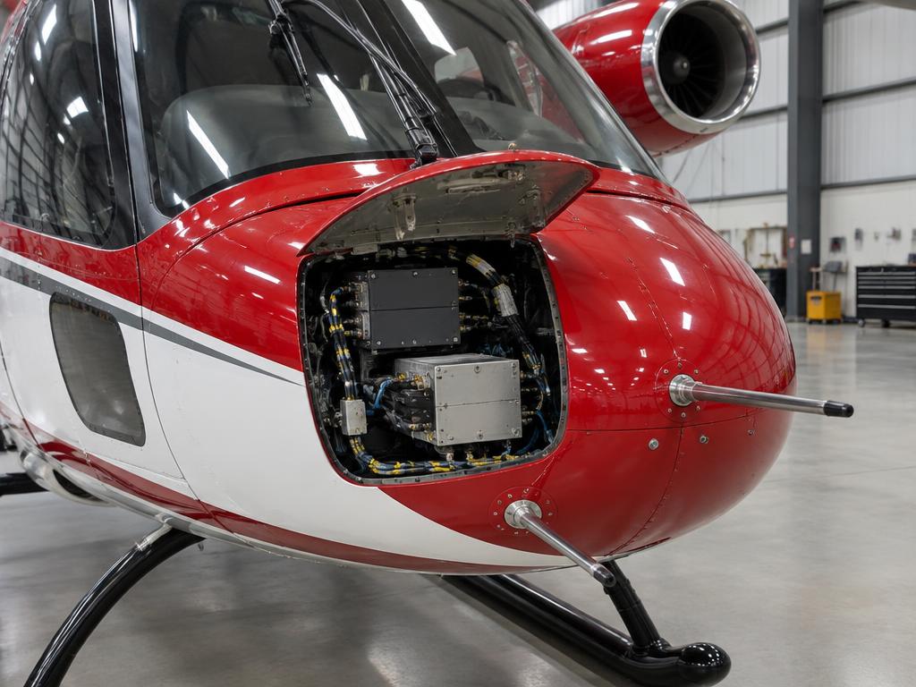
Nose avionics bay and pitot probes
Nose avionics bay and pitot probes · illustrative image

Three-screen Helionix glass cockpit with a 4-axis digital autopilot (AFCS) and conventional collective, cyclic and pedals.

  • Collective (with twist-grip throttle backup), cyclic and anti-torque pedals command the rotors through dual hydraulic-boosted flight controls; the cyclic and collective act on the main rotor's swashplate, the pedals change Fenestron blade pitch.
  • Helionix integrates three multifunction displays, a 4-axis autopilot (yaw, pitch, roll and collective/vertical), and a flight director with upper-modes (altitude, speed, heading, vertical speed, hover hold, approach).
  • The First Limit Indicator (FLI) combines torque, NG (gas generator speed), TOT (turbine outlet temperature) and NR (rotor speed) into a single needle so the pilot always sees the limiting engine parameter at a glance.
  • CAS (Crew Alerting System) messages replace individual annunciator lights, prioritised red (warning) / amber (caution) / white (advisory) on the lower MFD.
  • Can be flown single-pilot IFR (SPIFR) with the AFCS, or by two pilots for HEMS and offshore operations.

Safran Arriel 2E Turboshafts ATA 71, 72, 73, 74, 79

Where it is

Location of Safran Arriel 2E Turboshafts
Safran Arriel 2E Turboshafts

What it looks like

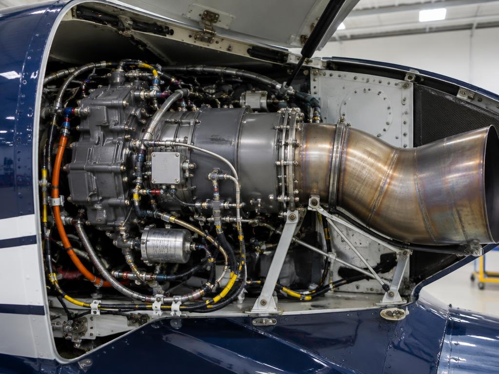
Arriel 2E turboshaft in its bay with the cowling open
Arriel 2E turboshaft in its bay with the cowling open · illustrative image

Two free-turbine turboshafts, each with dual-channel FADEC, driving the main gearbox with One-Engine-Inoperative (OEI) ratings for engine-out safety.

  • Each Arriel 2E is controlled by its own dual-channel FADEC, which schedules fuel flow and protects NG, TOT and NR automatically through all normal manoeuvres.
  • In twin-engine operation, torque is shared and limited to the All-Engines-Operative (AEO) rating; if one engine fails, the FADEC and the healthy engine automatically provide OEI power.
  • OEI ratings are time-limited: 30-second and 2-minute OEI for the immediate emergency, and a continuous (maximum continuous) OEI rating for the rest of the flight.
  • A freewheel unit on each engine output shaft lets a failed or shut-down engine's turbine stop turning (autorotation-compatible) while the other engine, or the rotor in full autorotation, continues to drive the gearbox.
  • Fuel is drawn from crash-resistant tanks low in the fuselage, with separate feed, boost pumps and crossfeed capability.

Main Rotor & Flight Controls ATA 62, 63, 67

Where it is

Location of Main Rotor & Flight Controls
Main Rotor & Flight Controls

What it looks like

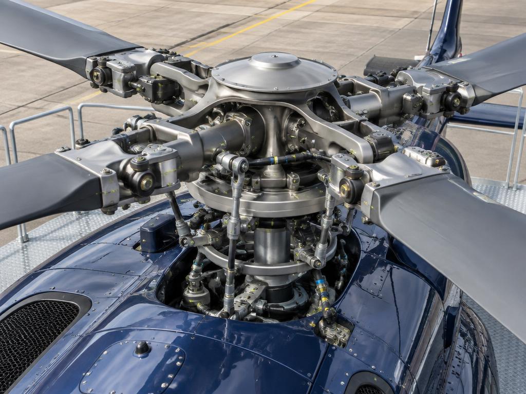
Hingeless main rotor head, pitch links and swashplate
Hingeless main rotor head, pitch links and swashplate · illustrative image

A bearingless, hingeless 4-blade main rotor (5-blade on the H145 D-3) with carbon-fibre blades, driven through the main gearbox and controlled by dual hydraulic boost.

  • The bearingless/hingeless main rotor head has no mechanical flapping or lead-lag hinges or elastomeric bearings on the D-2 — blade root flexures absorb those loads, reducing parts count and maintenance.
  • The main gearbox reduces engine output speed to main rotor RPM (NR) and also drives the tail rotor drive shaft to the Fenestron.
  • Two independent hydraulic systems boost cyclic, collective and pedal inputs at the servo actuators; either system alone can control the aircraft if the other fails.
  • Rotor RPM (NR) is a primary instrument: low NR risks rotor stall and loss of lift, high NR risks blade and mast overspeed — the FLI and NR gauge are monitored continuously, especially during autorotation.
  • In autorotation (total loss of engine power), the freewheel units disconnect the engines and the main rotor is driven by upward airflow through the disc; the pilot lowers collective immediately to maintain NR.

Skid Landing Gear ATA 32

Where it is

Location of Skid Landing Gear
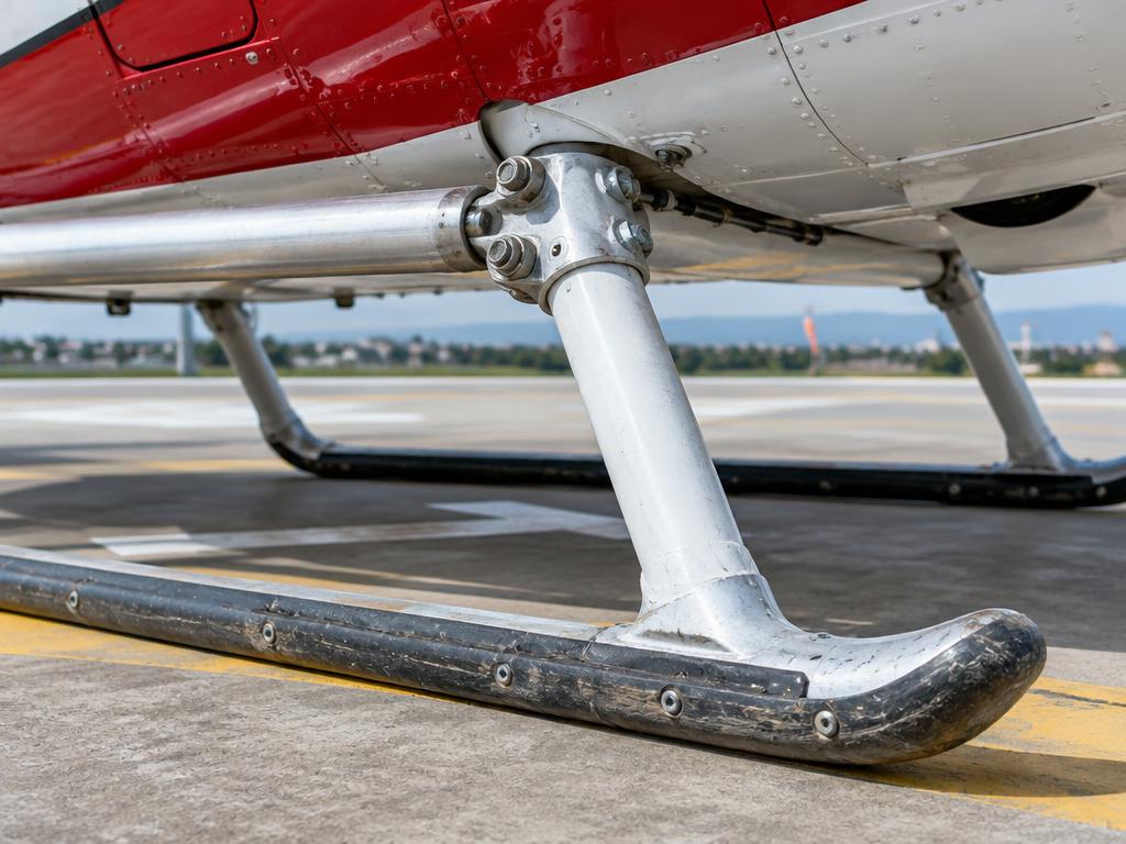
Skid Landing Gear

What it looks like

Skid gear: cross tube, skid tube and wear shoes
Skid gear: cross tube, skid tube and wear shoes · illustrative image

Fixed, cross-tube skid landing gear absorbing landing loads by flexing; wheeled ground-handling gear is optional for hangar moves.

  • The skids are fixed — there is no retraction system — and the cross-tubes flex elastically to absorb normal landing loads, including sliding landings and practice autorotations to the ground.
  • Because the gear is fixed, dynamic rollover is a real hazard: if a skid catches the ground or snow/uneven terrain while picking up or setting down with sideways cyclic input, the aircraft can roll over its skid before the pilot can react.
  • Ground handling wheels can be fitted temporarily to move the helicopter in a hangar or on a ramp; they are removed before flight.
  • Skid shoes (wear plates) are replaceable items that take the abrasion of ground contact.

Fuselage & Systems ATA 24, 28, 29, 53

Where it is

Location of Fuselage & Systems
Fuselage & Systems

What it looks like

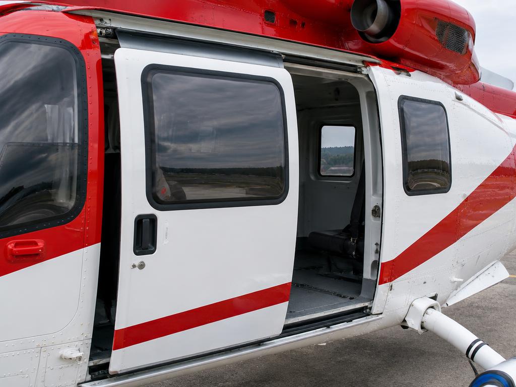
Sliding cabin door and fuselage side
Sliding cabin door and fuselage side · illustrative image

Composite and metal semi-monocoque fuselage housing the cabin, crash-resistant fuel system, electrical system and both hydraulic systems.

  • The cabin can be configured for HEMS (stretcher and medical equipment), police, utility or VIP transport, with a flat, unobstructed floor and large sliding doors/clamshell rear doors.
  • Electrical power is 28 VDC supplied by two engine-driven starter-generators plus a battery; this also starts each engine in turn.
  • Two independent hydraulic systems supply the boosted flight controls described under Main Rotor & Flight Controls; each system has its own reservoir and pump.
  • There is no APU and no cabin pressurization — the H145 is unpressurized and flown at altitudes where this is not required.
  • Crash-resistant fuel tanks and crashworthy seats/structure are designed to improve occupant survivability in a hard landing.

Fenestron & Tail Boom ATA 64, 65

Where it is

Location of Fenestron & Tail Boom
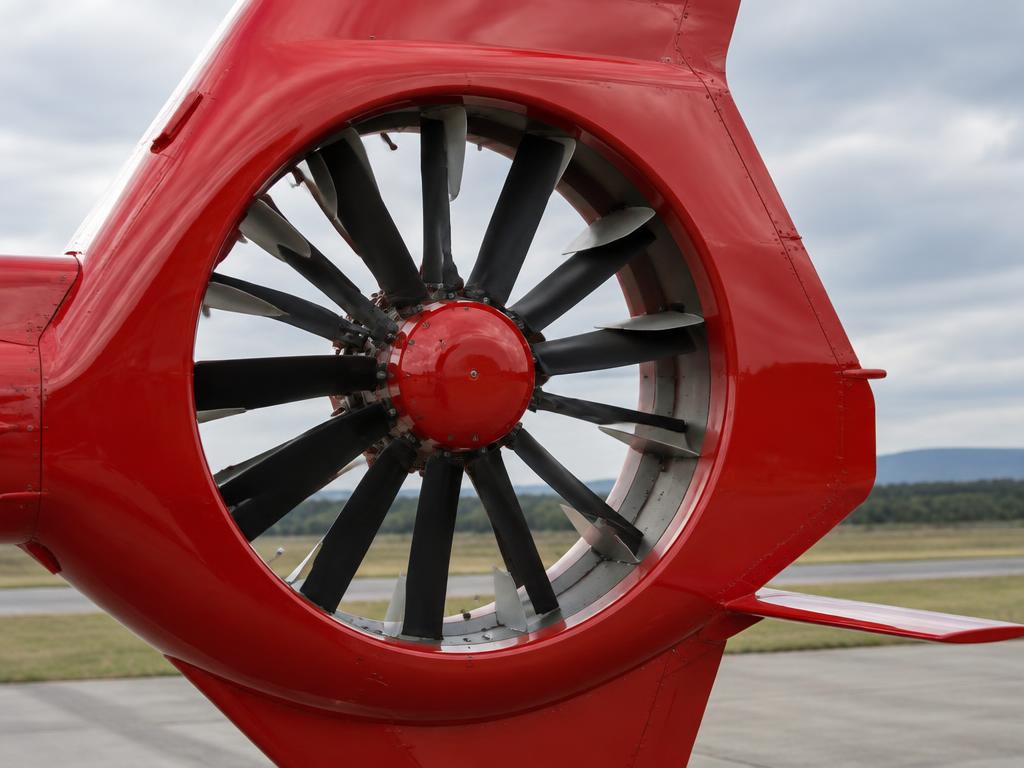
Fenestron & Tail Boom

What it looks like

Fenestron shrouded tail rotor with stator vanes
Fenestron shrouded tail rotor with stator vanes · illustrative image

A shrouded Fenestron fan in the tail boom provides anti-torque and yaw control, driven through a tail rotor drive shaft and tail gearbox.

  • The Fenestron is a multi-bladed fan enclosed in a duct built into the tail boom/fin, rather than an exposed tail rotor; pedal inputs change the pitch of its blades through the tail rotor control system.
  • Because the fan is shrouded, the H145 is markedly less exposed to Loss of Tail-rotor Effectiveness (LTE) in certain wind azimuths than helicopters with an open tail rotor, although anti-torque authority is still finite and must be respected in strong crosswinds/tailwinds and during low-speed manoeuvring.
  • A tail rotor drive shaft runs aft from the main gearbox through the tail boom to an intermediate and tail gearbox that turns the Fenestron fan.
  • The vertical fin itself provides some aerodynamic anti-torque assistance in forward flight, reducing the power the Fenestron must supply.
7A

Annunciators & Fault Messages

Open the interactive fault finder →

ENG 1 FIREFire detected in the No.1 (Arriel 2E) engine bay. Red CAS message, master warning, aural tone.
ENG 2 FIREFire detected in the No.2 engine bay.
ENG 1 FAIL / ENG 1 OUTNo.1 Arriel 2E has flamed out, failed to respond to throttle, or NG/TOT has collapsed. The aircraft is now single-engine (OEI).
ENG 2 FAIL / ENG 2 OUTNo.2 engine failure — aircraft now OEI on No.1.
FADEC 1 FAILBoth FADEC channels on engine 1 have failed — engine reverts to a fixed, degraded fuel schedule or may flame out.
FADEC 1(2) DEGRADED / CHANNEL FAULTOne FADEC channel (A or B) has failed on an engine; the other channel keeps controlling the engine normally.
MGB OIL PRESS LOMain gearbox oil pressure below limit — the MGB has a limited dry-running capability but cannot be relied on indefinitely.
MGB OIL TEMP HIMain gearbox oil temperature above limit.
MGB CHIPA metal particle has been detected on the main gearbox chip detector — early sign of internal gearbox distress.
TGB CHIPMetal particle detected at the tail gearbox (fenestron drive) chip detector.
IGB CHIPMetal particle detected at the intermediate gearbox, between the tail rotor drive shaft and the TGB.
ENG 1(2) CHIPMetal particle detected on an engine chip detector.
NR HIGHMain rotor speed above the normal operating band (approaching the overspeed limit), shown on the FLI/NR gauge.
NR LOWMain rotor speed below the normal operating band — loss of rotor energy, risk of stall and loss of control if not corrected immediately.
HYD 1 FAIL / HYD 1 PRESS LOHydraulic system 1 (of the two independent boost systems for the flight controls) has lost pressure.
HYD 2 FAIL / HYD 2 PRESS LOHydraulic system 2 has lost pressure; system 1 continues to boost the controls.
GEN 1 FAILNo.1 starter-generator has failed or been disconnected from the bus.
GEN 2 FAILNo.2 starter-generator has failed or been disconnected from the bus.
BAT HOT / BAT OVERTEMPBattery temperature above limit — risk of thermal runaway.
BAT DISCHARGEThe battery is supplying current rather than being charged — an abnormal discharge is in progress.
FUEL LOWUsable fuel quantity has reached the low-level threshold (approx. 15-min endurance reserve, configuration dependent).
FUEL PUMP 1(2) FAILA tank-mounted boost pump has failed; gravity/suction feed may still supply the engine at lower power or altitude but with reduced margin.
AFCS FAIL / AP DISCThe 4-axis AFCS (autopilot/stability augmentation) has disconnected or a channel has failed, shown with an aural tone and CAS message.
OEI LIMIT / 30 SEC-2 MIN RATING EXCEEDEDThe remaining engine has been operated beyond the time-limited OEI 30-second or 2-minute rating shown on the FLI, into territory requiring a post-flight engine inspection.
TOT EXCEEDANCE (ENG 1/2)Turbine outlet temperature has exceeded the limit for the selected rating (takeoff/MCP/OEI), shown as a red arc exceedance on the FLI/engine page.
PITOT HEAT FAIL / AOA/ASI HEAT FAILPitot (and/or static port) heater has failed to draw current when selected ON.
SMOKE / FUMES IN COCKPIT-CABINSmoke or burning smell detected in the cockpit or cabin, typically from an electrical or bleed-air source.
TAIL ROTOR DRIVE FAILURE (fenestron)Loss of drive to the fenestron shrouded tail rotor (shaft or gearbox failure) — loss of anti-torque with drive disconnected; behaviour differs from an open tail-rotor loss because the Fenestron is shrouded and less exposed to LTE, but a drive-train failure is still a yaw-control emergency.
Vortex ring state (recognised condition, not a CAS message)Settling with power: high rate of descent (typically >700-800 ft/min), low airspeed (<30 kt), with power applied — rotor is operating in its own downwash. Increasing collective makes it worse.
Dynamic rollover risk (recognised condition, not a CAS message)A skid (or one wheel on wheeled gear) becomes a pivot point during a sideways or cross-slope hover/takeoff, and bank angle can increase faster than the cyclic can correct, leading to rollover if collective is not reduced.
7B

Systems In Depth (engine, gear, controls…)

Deep dive · ATA 21

Heating, Ventilation & Air Conditioning — in depth

Cabin heat & bleed air

Cabin and cockpit heat is supplied from engine bleed air (or an electric heater element on some utility fits) through a mixing valve that blends hot bleed air with ambient ram/fan air to the selected temperature. There is no pressurisation system — the cabin is unpressurised and bleed air use is only for heating, demisting and (on some fits) de-icing/de-misting of the windscreen.

An optional air conditioning (vapour-cycle) pack, often fitted for HEMS/VIP configurations, uses an electrically or belt-driven compressor and evaporator in the cabin headliner; it is a stand-alone system separate from the heating bleed-air circuit.

Heat sourceEngine bleed air (mixed with ambient) or electric element
PressurisationNone — unpressurised cabin
Optional A/CVapour-cycle, electrically driven compressor
Windscreen demistHot air outlets at the lower windscreen

Ventilation

Fresh-air ventilation comes from cockpit/cabin eyeball vents fed by ram air (and a blower at low airspeed/on the ground) plus openable cabin windows on utility doors. Cabin crew/medical configurations often add dedicated fans for equipment cooling and patient-compartment airflow.

Fumes & smoke

A bleed-air or electrical heat fault can introduce fumes or overheat smells into the cabin; the QRH drill is to select heat/bleed OFF, increase fresh-air ventilation, and land as soon as practicable if smoke persists.

Warning · Treat any unexplained smoke or fume odour from the heating system as an emergency — do not continue troubleshooting airborne beyond the checklist actions.

Deep dive · ATA 22

Automatic Flight Control System (AFCS) — 4-axis autopilot in depth

Architecture

The Helionix AFCS is a 4-axis digital autopilot (pitch, roll, yaw and collective/torque) with dual-redundant flight control computers driving series/parallel actuators on the flight control runs. It provides both Stability Augmentation (SAS/rate damping, always-on low-authority stabilisation) and upper modes (attitude hold, heading, altitude, airspeed, vertical speed, navigation coupling, and approach/hover modes on suitably equipped aircraft).

Because the collective axis is included, the AFCS can hold a selected altitude or rate of climb/descent by adjusting collective pitch (and hence torque) as well as cyclic, which is a key difference from simpler 2- or 3-axis helicopter autopilots.

AxesPitch, roll, yaw, collective (torque)
Basic functionSAS / rate damping, always active in normal law
Upper modes (typical)ATT, HDG, ALT, IAS, V/S, NAV coupling, approach/hover modes (role-dependent)
RedundancyDual flight control computers, cross-monitored

Upper modes & crew interface

Upper modes are armed/engaged from a Flight Control Panel integrated with the Helionix MFDs; engaged and armed modes display on the PFD mode annunciator, similar in concept to a fixed-wing FMA but tailored to helicopter axes (e.g. HDG, ALT, IAS/VS, NAV, APP for a coupled approach, and hover modes such as position-hold on SAR/HEMS-optimised aircraft).

A 4-axis trim/beep system lets the pilot adjust the AFCS-held attitude/heading/altitude/airspeed with a four-way trim switch on the cyclic without having to disengage the autopilot.

Degradation & disengagement

Loss of one flight control computer typically downgrades the AFCS to a reduced mode set (e.g. basic SAS only) with a CAS caution, rather than a full autopilot failure, because of the dual-redundant architecture.

The autopilot can be disengaged instantly by the cyclic quick-release button, by large manual control force override (force-trim release), or by selecting AP OFF on the control panel; hand-flying after disconnection should be smooth since the SAS damping is lost along with the upper modes.

Warning · An AFCS hardover or uncommanded input is countered by prompt use of the quick-disengage button — know its location without looking, since hands-on reaction time matters more than diagnosing the cause in the moment.

Deep dive · ATA 24

Electrical Power — 28 VDC system in depth

Architecture

The H145 uses an unregulated 28 VDC, negative-ground system. Two engine-pad-mounted starter-generators (one per Arriel 2E, approx. 250 A each) supply the two main DC buses in flight; on the ground, external power or a ground power unit (GPU) can be used through a receptacle with reverse-current and over-voltage protection.

A single main battery (typically a 24 V, approx. 40 Ah NiCd or a sealed lead-acid pack) sits in a ventilated box, usually in the nose or aft fuselage compartment depending on fit, and supplies starting and essential/standby loads if both generators are lost.

Distribution is through BUS 1 and BUS 2 (each fed by its own starter-generator), an ESS (essential) bus, and a battery bus that stays live with the battery master on. A bus tie contactor allows either generator to back up the other bus. Helionix avionics, FADEC channels and critical flight instruments are split across BUS 1/2 and the ESS bus so no single generator loss blanks a full set of displays.

System voltage28 VDC nominal (approx. 28-29 V regulated)
Starter-generators2 x approx. 250 A, engine-pad driven
Main battery24 V, approx. 40 Ah (NiCd typical)
Bus architectureBUS 1 / BUS 2 / ESS / BATT bus with tie contactor
GPU receptacle28 VDC external power, reverse-current protected

Generator control & protection

A Generator Control Unit (GCU) per side regulates voltage, handles paralleling logic through the bus tie, and trips the generator off-line for over-voltage, under-voltage, feeder fault or reverse current, annunciated as a caution on the Helionix CAS (crew alerting system).

Loss of one generator: the bus tie closes automatically (or manually per checklist) so the remaining generator carries both buses; some non-essential loads may be shed automatically or by crew action to stay within the single generator's rated output, especially at high ambient temperature with full avionics and de-icing loads.

Battery operation & starting

  1. 1.Preflight: check battery temperature/voltage monitor (if fitted) and confirm no BATT caution.
  2. 2.Battery alone can motor and start one engine; cross-generator or GPU assist is preferred for the second start to limit battery depth-of-discharge and heating, particularly with a NiCd battery.
  3. 3.During engine start the FADEC and ignition draw from the battery/DC bus until the starter-generator on that engine comes on line and takes over as a generator.
  4. 4.After flight: confirm battery master is cycled per checklist before the aircraft is left unattended, since some Helionix equipment can stay powered on standby buses.

Failure analysis & CAS messages

GEN 1 (2) FAULTGenerator off line — bus tie picks up automatically; monitor remaining generator load
BATT FAULT / BATT TEMP HIPossible thermal runaway risk (NiCd) — follow QRH, consider battery disconnect
DC BUS 1 (2) FAULTBus unpowered — isolate affected equipment per CAS synoptic
EXT PWR ONGround power connected — inhibits some systems/engine start interlocks

Warning · A NiCd battery showing rising temperature and falling voltage in flight can be heading for thermal runaway — follow the emergency checklist (battery off) without delay.

Maintenance points

NiCd battery: capacity check and cell-by-cell inspection at scheduled intervals (electrolyte level, vent caps, inter-cell connections); a battery that has been deep-cycled or shows uneven cell voltages is removed for shop test per AMM/CMM.

Starter-generator brushes, feeder cable chafing at the engine deck, and bonding straps across the airframe are AMM inspection items; corroded bus-bar connections are a common source of intermittent CAS faults.

Deep dive · ATA 26

Fire Protection — in depth

Detection

Each engine bay has fire/overheat detection (continuous sensing element or point detectors) feeding the Helionix caution/warning system; detection is usually dual-loop for redundancy so a single detector fault does not mask a real fire or give a false warning.

An engine compartment fire triggers a dedicated FIRE ENG 1 (2) warning on the CAS with an aural alert; baggage/equipment bay smoke detectors may be fitted depending on role equipment (HEMS, VIP).

Extinguishing

Each engine bay is protected by a fire extinguisher bottle (typically one-shot, with a second bottle or a two-shot bottle arrangement on some installations) fired electrically from a guarded cockpit switch once the affected engine is shut down and its fuel/fire shutoff valve closed.

There is no APU and no cargo-hold fire-suppression system as such on the baseline H145 — fire protection is concentrated on the two engine bays, consistent with the twin-turboshaft, unpressurised design.

Engine fire bottles1-2 per engine bay depending on fit
AgentHalon-type (or halon-replacement on newer production)
Baggage/equipment smoke detectionRole-dependent (HEMS/VIP fits)

Engine fire procedure (teaching outline)

  1. 1.Identify the affected engine from the CAS message and engine instruments (TOT/NG/TRQ trend).
  2. 2.Confirm single-engine flight is sustainable using OEI charts; plan a landing.
  3. 3.Affected engine: condition lever/FADEC to shutdown position (or emergency engine shutoff per type), fuel firewall shutoff valve CLOSED.
  4. 4.Fire extinguisher bottle DISCHARGE if the fire warning persists.
  5. 5.Land as soon as possible; brief for a single-engine (OEI) approach and landing.

Warning · Teaching outline only — always follow the approved H145 RFM/QRH emergency procedure for engine fire.

Deep dive · ATA 28

Fuel System — in depth

Tanks & supply

Crashworthy, self-sealing bladder tanks under the cabin floor: a main/forward tank and an aft (or left/right, depending on fit) tank feeding a common supply tank that in turn feeds both engines, so a single fuel source serves both Arriel 2E engines through independent feed lines with shutoff valves.

Optional auxiliary tanks extend range for offshore/utility missions. Gravity and submerged electric boost pumps transfer fuel from the main cells into the supply tank; each engine has its own low-pressure feed line with a firewall shutoff valve operated from the cockpit.

Usable fuel (typical D-2)approx. 700 kg (standard tanks)
Fuel typeJet A / Jet A-1 / JP-8
Boost pumpsSubmerged electric, 2 per supply arrangement
Low fuel cautionApprox. 60-90 kg per side, per RFM
Firewall shutoff valves1 per engine, guarded cockpit switches

Flow path

  1. 1.Fuel transfers by electric boost pump (with gravity backup) from the main cell(s) into the supply tank.
  2. 2.From the supply tank, submerged pumps feed each engine's low-pressure line through a fuel filter with a bypass and a clog (differential pressure) indicator.
  3. 3.The engine-driven HP pump and the FADEC-controlled metering unit (on the Arriel 2E) then schedule fuel to the combustion chamber.
  4. 4.A cross-feed/interconnect allows one side to supply both engines if a pump or line fails on the other side, per the fuel synoptic on the Helionix MFD.

Indications & operating rules

The Helionix fuel synoptic shows tank quantities, transfer pump status and any LOW FUEL or fuel imbalance caution. Crews cross-check gauges against a calibrated dipstick or capacitance-probe test before flights where fuel state is critical (e.g. offshore, HEMS standby).

Fuel filter clog indicators (bypass) must be checked at each refuel/inspection — a popped indicator shows contamination is being bypassed unfiltered to the engine.

Warning · Never dispatch with a popped fuel filter bypass indicator uninvestigated — unfiltered fuel can damage the FADEC metering unit or fuel nozzles.

Maintenance

Water/sediment drainDaily, at tank and filter low points
Filter elementReplace per AMM interval or on bypass indication
Bladder tank inspectionVisual for chafing, correct strap/restraint per AMM, crashworthy fittings undamaged
Pump operational checkVerify pressure/flow on ground run or BITE test

Deep dive · ATA 29

Hydraulic System — in depth

Dual hydraulic architecture

Two independent hydraulic systems (System 1 and System 2) each driven by its own pump off the main gearbox accessory drive, boosting the flight controls (cyclic, collective and pedal servo-actuators). Either system alone can fly the aircraft; running both together shares the load and gives redundancy, not more authority.

Each system has its own reservoir, pressure relief, filtration and a pressure transmitter feeding the Helionix hydraulic synoptic, which shows pressure, reservoir level/temperature and pump status for both systems.

Systems2 independent, each with own pump off the MGB
FluidMineral-based hydraulic fluid per AMM (e.g. MIL-H-83282 type or manufacturer-specified)
Reservoirs1 per system, sight gauge or electrical level sensor
Servo-actuators boostedCyclic, collective, pedal (tail rotor/Fenestron control)

Degraded modes

Loss of one hydraulic system: the remaining system continues to boost all primary flight controls; the crew sees a HYD 1 (2) FAULT caution and flies with reduced redundancy, usually with no handling restriction beyond checklist cautions on manoeuvring.

Dual hydraulic failure is a rare, severe case: control forces rise sharply (the bearingless rotor and large control loads make unboosted flight very heavy) and the RFM gives specific speed/configuration guidance; this is one of the most demanding emergencies trained in the simulator.

Warning · Dual hydraulic failure produces very high control forces — do not attempt aggressive manoeuvring; follow the RFM emergency procedure and land as soon as possible.

Maintenance

Reservoir level checkDaily/preflight, per sight gauge or synoptic
Filter conditionClog indicators checked at inspection interval
Accumulator/pressure checkGround run per AMM, confirm pressure within limits
Fluid contaminationParticle count sample per scheduled maintenance

Deep dive · ATA 30

Ice & Rain Protection — in depth

Windshield & pitot/static

Electrically heated windshield panels (on IFR/full-de-ice-kit aircraft) prevent icing and fogging; pitot tubes, static ports and the AOA/outside air temperature probes used by the air data system are electrically heated and selectable from the cockpit, with a CAS caution if heating current is abnormal (open circuit or short).

Main and tail rotor (Fenestron) de-icing (optional kit)

On aircraft fitted with the optional de-icing/anti-icing system, electrical heater mats bonded to the main rotor blade leading edges and the Fenestron blades are sequenced by a de-ice controller to shed ice in a programmed cycle rather than continuously melting it, which would waste power and risk uneven shedding and vibration.

An ice detector probe (vibrating-rod type) senses ice accretion rate and feeds the controller/crew alerting logic; without the optional kit, the H145 is limited to flight outside forecast/actual icing conditions per the RFM limitations.

Pitot/static heatElectric, cockpit selectable, CAS monitored
Windshield heatElectric panels (as fitted)
Rotor de-ice (optional)Electrothermal, cyclic shedding sequence
Ice detectionVibrating-rod ice detector probe

Operating considerations

Even with the optional kit, icing severity, temperature range and holdover guidance in the RFM/limitations must be respected; unprotected areas (engine inlets without the kit, for example) remain icing-critical and engine inlet anti-ice/particle separator status should be checked per role equipment.

Warning · Flight into icing conditions without the certified de-ice kit installed and serviceable is outside the RFM limitations.

Deep dive · ATA 31/34

Avionics — Helionix integrated avionics suite

System architecture

Helionix is Airbus Helicopters' integrated avionics suite built around three identical Multi-Function Displays (MFDs, typically two primary plus a central MFD) that can each show any combination of Primary Flight Display (PFD), navigation map, engine/systems synoptic or checklist page — full reversion is possible if a display fails.

Two (or more) Flight Control & Display Computers host the symbol generation, AHRS/air data fusion, the 4-axis AFCS (autopilot) and the CAS (crew alerting system) logic. Dual AHRS and dual air data modules feed both pilot sides so a single sensor failure does not blank both displays.

A dedicated FADEC interface brings engine parameters (NG, NF/NR, TOT, TRQ) onto the engine instrument page, and the fuel, hydraulic, electrical and flight control systems each have a synoptic page selectable from the MFD bezel keys.

Displays3 x MFD (typically interchangeable)
Computers2 (or more) Flight Control & Display Computers
AFCS4-axis (pitch, roll, yaw, collective) digital autopilot
SensorsDual AHRS, dual air data, dual GPS typical
CASCrew Alerting System — Warning/Caution/Advisory colour-coded messages

Display reversion & CAS logic

If a display or computer fails, the system reconfigures so flight-critical information (attitude, airspeed, altitude, engine first-limit) is preserved on the remaining display(s), following a defined reversion priority rather than simply blanking.

CAS messages are organised by colour/urgency: red Warning (immediate action, usually with an aural tone), amber Caution (crew awareness, action may be required), and white/cyan Advisory or status. A master caution/warning panel and a dedicated CAS page keep a scrollable log of active and cleared messages.

Flight management & navigation

An integrated FMS (flight management function) provides route/flight-plan management, coupled with GPS and the AFCS for IFR and SAR/HEMS-pattern navigation (e.g. coupled search patterns, hover trajectory modes on suitably equipped aircraft). Moving-map, terrain awareness (HTAWS) and, on many fits, an obstacle/terrain database are presented on the MFD.

Maintenance considerations

Software/database (navigation, terrain) updates are loaded via a data-loader interface at scheduled cycles. Built-in test (BITE) on the Flight Control & Display Computers logs faults for troubleshooting; sensor calibration (AHRS, magnetometer) is required after certain structural or avionics maintenance, similar to any strapdown AHRS installation.

Deep dive · ATA 62

Main Rotor — bearingless/hingeless rotor system in depth

Design concept

The H145 (D-2) uses a 4-blade, hingeless, bearingless main rotor hub (Airbus Helicopters' signature design lineage from the BK117/EC145 family); the D-3 variant uses a 5-blade rotor of similar bearingless philosophy. 'Bearingless' means flap, lag and pitch motions are all accommodated by composite flexbeam/torque-tube flexure rather than mechanical hinges or elastomeric bearings at a hinge point — simplifying the hub and reducing parts count and maintenance compared to an articulated rotor.

Each blade attaches through a composite flexbeam that is rigidly fixed to the hub at the root but flexes to allow flapping and lead-lag; a torque tube surrounding the flexbeam carries pitch-control loads from the pitch links to the blade, driven by the swashplate.

Configuration (D-2)4-blade, hingeless, bearingless, composite hub
Configuration (D-3)5-blade, bearingless (variant)
Blade materialComposite (glass/carbon fibre), replaceable tip cap and erosion strip
Rotor speed NR (100%)Per RFM placard, typically in the 260-300 RPM class (type-specific)

Loads, vibration and handling implications

A hingeless/bearingless hub transmits more hub moment to the fuselage than a fully articulated rotor, giving crisp control response and good gust/turbulence damping, at the cost of higher structural loads that the composite flexbeam is specifically designed to absorb through its own flexibility.

A health and usage monitoring system (HUMS) tracks rotor track-and-balance and vibration trends; track-and-balance adjustments use trim tabs and (on some fits) active vibration control rather than traditional hinge-pin shimming, since there are no flap/lag hinges to adjust.

Rotor RPM (NR) management

NR is managed automatically by the engines' FADECs working together (load-sharing) to hold rotor speed within the normal operating band through the collective pitch range; the pilot primarily monitors NR on the Helionix first-limit-type display alongside TRQ, NG and TOT rather than manually governing it as on some older types.

Low NR (e.g. following a dual-engine issue or in autorotation if not managed) is one of the most serious conditions in a helicopter — insufficient rotor energy quickly degrades control and lift; autorotation technique (lowering collective promptly to maintain NR) is a core emergency skill.

Warning · Low rotor RPM is an immediate, severe hazard — lowering collective to restore/maintain NR takes priority over almost every other action in an engine failure.

Inspection points

FlexbeamVisual/NDT for delamination, cracking at root per AMM interval
Blade erosion strip/tip capCheck for disbonding, erosion beyond limits, lightning strike damage
Pitch links/torque tubeSecurity, wear, correct rigging
Track and balanceHUMS vibration trend review, adjust trim tabs as required

Deep dive · ATA 63

Main Gearbox (MGB) — in depth

Function & construction

The main gearbox reduces the high engine output speed (NF, free-turbine speed) from both Arriel 2E engines down to main rotor shaft speed, and combines the power of both engines through input freewheel units so that a stopped or failed engine's input is automatically declutched (one-way clutch) without crew action.

A tail rotor drive takeoff from the MGB sends power aft to the Fenestron drive shaft; accessory drives from the MGB also run the main hydraulic pumps and, on some fits, a generator or alternator pad.

FunctionCombines 2 engine inputs via freewheels, reduces to NR, drives tail takeoff
Freewheel units1 per engine input, automatic overrun/declutch
LubricationDedicated oil system with pump, filter, cooler
OEI ratings used by MGBRated to accept 30-sec, 2-min and continuous OEI torque

Lubrication & monitoring

A dedicated MGB oil system (its own pump, filter and oil cooler, often with a cooling fan) lubricates and cools the gear mesh and bearings; oil pressure, temperature and (critically) chip detector status are displayed on the Helionix systems synoptic.

Chip detectors are magnetic plugs in the sump that catch ferrous wear debris; some are 'burn-off' type that can clear a single fine chip electrically before triggering a caution, while a persistent or second indication is a serious maintenance/flight safety event.

OEI (One Engine Inoperative) ratings

The MGB, like the engines, is rated for OEI operation: a 30-second rating for the immediate failure transient, a 2-minute rating to allow a safe approach/landing, and a continuous (max continuous OEI) rating for extended single-engine flight — these torque limits are placarded and tracked by the FADEC/Helionix first-limit indicator.

Warning · An MGB chip detector caution, especially if it recurs or is accompanied by abnormal noise/vibration or oil pressure/temperature trends, calls for an immediate precautionary landing per the RFM — the gearbox has no backup if it fails.

Inspection points

Oil level/sight gaugePreflight check against minimum mark
Chip detectorsInspect for debris at each interval; analyze metal type
Mounting/suspensionCheck gearbox isolation mounts and attachment fittings for cracks
Output flangesCheck main rotor mast and tail drive flange for play/spline wear

Deep dive · ATA 64/65

Fenestron Shrouded Tail Rotor & Tail Rotor Drive — in depth

Fenestron concept

The Fenestron is a multi-bladed (typically 10+ unevenly spaced composite blades) shrouded fan set into the tail fin, replacing a conventional exposed tail rotor. The shroud (fin duct) both protects ground personnel and the blades themselves, and recovers some thrust aerodynamically from the duct, improving efficiency at a given anti-torque thrust compared with an open rotor of similar diameter.

Uneven blade spacing (variable angular pitch between blades around the fan) spreads the acoustic tones across frequencies rather than one dominant blade-passage tone, giving the Fenestron's characteristically different, less penetrating noise signature versus a conventional tail rotor.

TypeShrouded, multi-bladed fan (Fenestron) in the vertical fin
Blade countTypically 10+ composite blades, unevenly spaced
Pitch controlCollective pitch change via pedal input through a spider/pitch-change mechanism
HousingIntegral with the vertical fin structure

Tail rotor drive

Power reaches the Fenestron from the MGB tail takeoff through an intermediate (tail) drive shaft running aft along the tail boom, supported by hanger bearings, to an intermediate gearbox (if fitted) and then a tail (Fenestron) gearbox that turns the drive through the final angle and reduces speed for the fan.

Hanger bearing condition, shaft balance and coupling alignment are flight-safety items — a failed hanger bearing can allow shaft whip and eventual drive-shaft failure, which would be a loss of anti-torque authority.

Anti-torque handling notes

Because the Fenestron is shrouded, classic Loss of Tail Rotor Effectiveness (LTE), a hazard associated with exposed tail rotors in certain wind azimuths, is much less of a concern on the H145 — though yaw control authority still has normal limits (e.g. reduced pedal margin at high gross weight, high density altitude, or strong crosswind/tailwind hover), and the pedal/yaw handling qualities differ somewhat from an open tail rotor due to duct aerodynamics.

A Fenestron drive or control failure is handled as a tail rotor (anti-torque) emergency per the RFM — typically requiring a running landing at an airspeed where aerodynamic weathervaning provides directional stability, since hover without yaw control is not controllable.

Warning · Total loss of tail rotor (Fenestron) drive or control normally requires a run-on landing at speed, not a hover — attempting to hover without anti-torque control will result in an uncontrolled spin.

Inspection points

Fenestron bladesLeading edge erosion, delamination, foreign object damage, security of pitch horns
Tail drive shaft/hanger bearingsVibration/noise check, bearing play, coupling condition
Tail gearbox oilLevel, chip detector, leaks
Pitch-change mechanismSpider/bearing wear, pedal rigging check

Deep dive · ATA 67

Rotor Flight Controls — in depth

Primary controls

Collective pitch lever (with integral throttle/engine control logic, largely automatic under FADEC) changes the pitch of all main rotor blades together to control thrust/lift; cyclic stick tilts the swashplate to vary blade pitch cyclically through each revolution, tilting the rotor disc for pitch and roll; the pedals control Fenestron collective pitch for yaw/anti-torque.

All three control axes are hydraulically boosted through servo-actuators (fed by the dual hydraulic systems) acting on a fixed/rotating swashplate assembly for cyclic and collective, and on the Fenestron pitch-change spider for the pedals.

CollectiveLever input -> swashplate vertical movement -> all blades pitch together
CyclicStick input -> swashplate tilt -> cyclic blade pitch change, 1-per-rev
PedalsFenestron collective pitch change for yaw/anti-torque
BoostHydraulic servo-actuators, dual system, see ATA 29

Mixing with AFCS and FADEC

The AFCS (ATA 22) introduces trim and stabilisation inputs into the same control runs via series/parallel actuators, so the pilot sees the controls move slightly with SAS activity without feeling the raw forces; force-trim/release and the 4-way beep trim let the pilot reposition the AFCS-held datum smoothly.

Collective position and rate also feed the FADEC load-sharing logic so engine torque is coordinated between both engines as power demand changes — a benefit of the integrated digital engine/flight control design versus older purely mechanical linkages.

Degraded/manual reversion

With full hydraulic boost lost on both systems (dual hydraulic failure), controls remain mechanically connected but become very heavy; with partial system loss, the remaining hydraulic system continues to boost normally. There is no fully manual (unboosted) rotor-control mode intended for sustained flight given the loads involved in a bearingless rotor design.

Warning · Any binding, jam or abnormal friction reported in cyclic, collective or pedal controls must be treated seriously before flight — a jammed flight control is not a condition the AFCS can compensate for.

Inspection points

Pitch links/swashplate bearingsPlay, lubrication, security per AMM
Control riggingRange of travel and neutral position checks per inspection interval
Servo-actuator attach pointsSecurity, leaks, bushing wear
Force-trim/AFCS actuatorsOperational test and BITE check

Deep dive · ATA 71/72

Powerplant — Safran Arriel 2E turboshaft engines

Engine architecture

Two Safran Arriel 2E free-turbine turboshaft engines, each with a single-stage centrifugal compressor (often preceded by an axial stage in the 2-series, giving an axial-centrifugal compressor arrangement), an annular combustion chamber, a gas generator turbine driving the compressor (NG), and a separate free power turbine (NF) driving the main gearbox through a reduction gear train — mechanically decoupled from the gas generator so each spool can run at its own optimum speed.

Each engine is a complete, independent powerplant with its own oil system, fuel control (via dual-channel FADEC — see ATA 73) and accessory gearbox; the two engines are combined only downstream at the main gearbox through separate freewheel units (ATA 63).

TypeFree-turbine turboshaft, axial-centrifugal compressor
SpoolsGas generator (NG) + free power turbine (NF), mechanically independent
Power rating classApprox. 700-900 kW class per engine (OEI-rated variant 2E)
Engine parameters shownNG (%), NF/NR, TOT (turbine outlet temperature), TRQ (torque)

Ratings & FLI (First Limit Indicator)

The Arriel 2E is specifically optimised for strong One Engine Inoperative (OEI) performance: it has distinct takeoff/maximum continuous two-engine ratings plus 30-second, 2-minute and continuous OEI ratings used after an engine failure, each with its own TOT/TRQ/NG limit combination.

A First Limit Indicator (FLI) on the Helionix engine page condenses NG, TOT and TRQ into a single percentage-style gauge or bar showing the parameter closest to its limit for the selected rating, so the pilot manages one indication instead of cross-checking three separate gauges under workload (e.g. during an OEI event).

Starting & operating limits

  1. 1.Battery/GPU or cross-start power available; condition lever/FADEC mode selected to IDLE/start enabled per type procedure.
  2. 2.Starter motors the gas generator (NG); at a defined NG the FADEC schedules fuel flow and ignition automatically (Full Authority Digital Engine Control manages the whole light-off and acceleration).
  3. 3.FADEC monitors TOT during start and will limit/abort fuel flow if a hot start trend is detected, protecting the turbine from overtemperature.
  4. 4.Engine stabilises at ground idle NG; the pilot brings NR/NG to flight idle and checks parameters before increasing collective for lift-off.

Warning · A hot start (rapid TOT rise above limits) must be aborted immediately per the emergency checklist even though FADEC provides automatic protection — do not rely solely on automation during an abnormal start indication.

Maintenance considerations

Engine health monitoring (vibration, trend data on NG/TOT/TRQ for a given power setting) feeds HUMS for condition-based maintenance; compressor washes, filter/particle separator servicing and borescope inspections of the hot section are scheduled per the engine maintenance manual.

Deep dive · ATA 73

Engine Fuel & Control — Dual-Channel FADEC in depth

FADEC architecture

Each Arriel 2E has its own dual-channel Full Authority Digital Engine Control (FADEC), with two independent electronic channels (often Channel A/B) each capable of fully controlling the engine; a channel swap occurs automatically on fault detection with no pilot action required for normal single-channel faults.

The FADEC meters fuel flow via an electrically controlled metering unit, schedules the fuel/air ratio through start and all power settings, manages the engine's contribution to NR governing in concert with the other engine's FADEC (load-sharing/rotor speed governing so both engines share torque evenly and NR is held steady), and provides automatic protections (overspeed, overtemperature, flame-out detection).

Channels per engine2 (dual-channel FADEC), automatic swap on fault
Key functionsFuel metering, start sequencing, NR/load-sharing governing, limit protection
InterfacesHelionix engine display (FLI), CAS messages, HUMS data recording
BackupMechanical/manual reversion is very limited or not provided — modern FADEC-only control

Load-sharing & rotor governing

The two FADECs communicate (directly or via the avionics) so that when collective pitch is raised, both engines increase torque together and rotor speed (NR) is held within its governed band automatically — the pilot does not manually set a throttle split as on older twin-engine helicopters.

If one engine's FADEC detects a fault and that engine spools down or is shut down, the remaining engine's FADEC automatically transitions power up to the appropriate OEI rating to keep NR and lift within limits, subject to the aircraft's weight and the margins published in the RFM.

Caution/warning logic

FADEC 1 (2) FAULTSingle-channel fault, automatic channel swap, engine control unaffected
FADEC 1 (2) FAILBoth channels affected — serious, engine control may be degraded/lost
ENG 1 (2) OEIEngine operating in an OEI-rated regime — monitor FLI and time limits (30s/2min)
NR LOW/HIGHRotor speed outside normal band — immediate collective/control action required

Warning · A dual-channel FADEC failure on one engine is a serious abnormal — follow the RFM procedure exactly; do not assume the second channel will recover on its own.

Maintenance considerations

FADEC software standard and engine trim data are configuration-controlled per aircraft; BITE fault history is downloaded at scheduled maintenance to catch intermittent channel faults before they become a dispatch issue, and FADEC/engine rigging checks follow the engine maintenance manual after any fuel control component change.

Deep dive · ATA 79

Oil System — Engine & Gearbox Lubrication in depth

Engine oil system (per Arriel 2E)

Each engine has its own self-contained, pressure-fed lubrication system with an engine-driven pump, filter (with bypass/clog indicator), air-cooled or fuel-cooled oil cooler, and scavenge pumps returning oil from the bearing sumps to the tank; magnetic chip detectors (often burn-off type) sit in the scavenge lines to catch ferrous debris from bearing or gear wear.

Oil quantity, pressure and temperature for each engine are shown on the Helionix engine/systems page, with low-pressure or high-temperature cautions driven by the FADEC/sensor network rather than simple mechanical gauges alone.

System typePressure-fed, dry-sump style, per engine
Chip detectorsMagnetic, often burn-off type, per engine and separately for MGB
Oil coolingAir or fuel-cooled oil cooler per engine
MonitoringPressure, temperature, quantity on Helionix synoptic

Main gearbox oil system

Separate from the engine oil systems, the MGB has its own oil supply, pump, filter and cooler (often with an electric or gearbox-driven cooling fan) sized to handle the combined heat generated by gear meshes carrying both engines' power — critical since the MGB has no equivalent of an engine shutdown to protect itself if oil is lost.

An MGB is typically certified to run for a defined period after indicated loss of oil pressure (a 'run-dry' capability, often around 30 minutes depending on certification basis) specifically to allow time to reach a safe landing area — a major safety feature for overwater/HEMS operations, though the exact time must be taken from the approved RFM, not assumed.

Warning · Do not assume a specific run-dry time without checking the approved H145 RFM for the installed MGB configuration — treat any MGB oil pressure loss as requiring an immediate landing at the nearest suitable site.

Chip detection & oil analysis

Fine, burn-off-type chip detectors can clear a single small chip without a flight-deck indication; a repeat indication (the detector has burned off and caught debris again) or a detection on a non-burn-off detector is a stronger signal of an active wear problem and drives maintenance action per AMM, often including oil sampling/spectrometric analysis and borescope or filter debris analysis.

Inspection points

Engine oil levelPreflight check against sight gauge/dipstick, each engine
MGB oil level & chip detectorsPreflight check; inspect debris if any indication
Filter bypass indicatorsCheck not popped at each servicing
Oil cooler/fanCheck for debris blockage, fan operation on ground run
8A

Maintenance Task Cards

Main battery inspection & capacity check

ATA 24 · Per AMM interval (and daily voltage/temperature check)

Access · Battery compartment access panel

Tools & materials · Digital multimeter · Battery capacity tester · Terminal cleaning kit · Torque wrench

Warning · A NiCd battery with rising temperature or falling voltage trend can indicate incipient thermal runaway — do not return a suspect battery to service without shop test.

  1. 1.Battery master OFF; disconnect battery per AMM sequence (negative first on removal).
  2. 2.Inspect the battery box for corrosion/electrolyte residue; clean and neutralise as required.
  3. 3.Check terminal condition, inter-cell connections (NiCd) and vent/drain paths are clear.
  4. 4.Perform or schedule a capacity check per AMM interval; check individual cell voltages if applicable.
  5. 5.Reinstall and reconnect per AMM sequence, torque terminals, verify no BATT FAULT caution on power-up.
CapacityReplace/refurbish below AMM-specified percentage of rated capacity
Cell voltage spread (NiCd)Per AMM acceptance limits

Ref: H145 AMM 24-30-00

Fuel filter inspection & bypass indicator check

ATA 28 · Per AMM interval and whenever bypass indicator shows popped

Access · Fuel filter housing, each engine supply line

Tools & materials · Filter wrench · New O-rings/seals · Fuel sample container

Warning · A popped bypass indicator means fuel has been flowing unfiltered to the engine — do not clear the indication without inspecting and, if needed, replacing the element.

  1. 1.Confirm fuel shutoff valve CLOSED for the line being serviced; relieve any residual pressure per AMM.
  2. 2.Remove the filter bowl/element and inspect the bypass (clog) indicator button position.
  3. 3.Inspect the filter element for contamination (water, debris, microbial growth); clean the bowl.
  4. 4.Install a new element/seals as required; reinstall and torque per AMM.
  5. 5.Reopen the shutoff valve, run an engine or boost pump per AMM to check for leaks and confirm the bypass indicator resets.
Bypass indicatorMust be reset (not popped) before return to service
ContaminationNo free water or debris after servicing

Ref: H145 AMM 28-20-00

Hydraulic reservoir level check (System 1 & 2)

ATA 29 · Daily / before first flight

Access · Hydraulic reservoirs, upper fuselage/MGB deck

Tools & materials · Flashlight · Approved hydraulic fluid

Warning · Never mix hydraulic fluid types — contamination can damage seals across both systems.

  1. 1.With the system in the depressurised/ground state specified by the AMM, read each reservoir's sight gauge or electrical level indication.
  2. 2.Compare to the minimum mark for System 1 and System 2 independently — do not assume one reading applies to both.
  3. 3.Top up with approved fluid if below minimum; do not mix fluid types.
  4. 4.Check for external leaks at reservoir fittings, lines and servo-actuators.
  5. 5.Record readings; investigate any system showing a trend of fluid loss.
Minimum reservoir levelPer AMM sight gauge/sensor mark, each system independently

Ref: H145 AMM 29-00-00

Skid landing gear inspection

ATA 32 · Daily/preflight visual, detailed per AMM interval

Access · Skid tubes, cross tubes, ground

Tools & materials · Flashlight · Inspection mirror · Torque wrench for attachment fittings

Warning · Any suspected hard or hard-side landing requires the AMM hard-landing inspection before further flight, even if the skid gear looks superficially normal.

  1. 1.Visually inspect skid tubes for dents, scoring, abrasion from ground contact, and corrosion.
  2. 2.Inspect cross tube attachment fittings to the fuselage for cracking, loose fasteners, and correct torque striping.
  3. 3.Check ground-handling wheel attachment points (if fitted) and any skid shoes/wear plates for wear.
  4. 4.Inspect for signs of a hard landing (cross tube bowing, fuselage skin wrinkling near attachments) and cross-reference with any hard-landing inspection requirement.
  5. 5.Record findings; defer per AMM damage limits or escalate to a hard-landing inspection if indicated.
Skid tube dents/scoringPer AMM damage limit chart
Cross tube deformationNone allowed beyond AMM limits — triggers hard-landing inspection

Ref: H145 AMM 32-00-00

Main rotor blade inspection

ATA 62 · Daily/preflight visual, detailed per AMM interval

Access · Main rotor blades, ground, rotor stopped

Tools & materials · Flashlight · Inspection mirror · Blade damage limit chart

Warning · Never rotate the rotor by hand to inspect a blade without confirming engines are shut down and all ignition/battery switches are set per the AMM ground-handling procedure.

  1. 1.Visually inspect each blade leading edge erosion strip for nicks, disbonding and lightning strike damage.
  2. 2.Check blade skin for delamination, cracking, or impact damage, especially near the root flexbeam area.
  3. 3.Inspect tip cap and balance weights for security.
  4. 4.Check drain holes (if fitted) are clear.
  5. 5.Compare any damage found against the AMM blade damage limit chart; record and defer or repair as required.
Leading edge erosionPer AMM blade damage limit chart
DelaminationNone beyond chart limits without repair

Ref: H145 AMM 62-10-00

Main gearbox oil level & chip detector check

ATA 63 · Daily / before first flight

Access · MGB access panel, upper fuselage

Tools & materials · Flashlight · Chip detector removal tool · Clean lint-free cloth

Warning · A persistent or repeat chip indication is a flight-safety item — do not dispatch without following the AMM/RFM fault isolation procedure.

  1. 1.Check MGB oil sight gauge/level sensor reading against minimum mark.
  2. 2.Remove each chip detector plug per AMM; inspect for metal particles.
  3. 3.If debris found, identify material (ferrous/non-ferrous) and compare against AMM acceptance criteria.
  4. 4.Reinstall plug with new seal, torque and safety per AMM.
  5. 5.Record findings; escalate per AMM if chips exceed limits.
Minimum oil levelPer AMM sight gauge/sensor
Chip detector debrisPer AMM acceptance limits — any significant metal is cause for investigation

Ref: H145 AMM 63-21-00

Fenestron blade inspection

ATA 64 · Daily/preflight visual, detailed per AMM interval

Access · Tail fin Fenestron duct, ground

Tools & materials · Flashlight · Inspection mirror · Torque wrench for access panels

Warning · Keep hands and tools clear of the duct interior until it is confirmed the rotors cannot be moved — residual rotation energy and inadvertent engagement are hazards.

  1. 1.Remove/open the fin access panel as required for the inspection level.
  2. 2.Visually inspect each Fenestron blade for leading-edge erosion, impact damage, and pitch-horn security.
  3. 3.Check the duct/shroud interior for cracks, delamination and foreign object debris between blades and duct wall.
  4. 4.Check blade pitch-change spider and linkages for play and correct lubrication.
  5. 5.Close and secure panels; record findings.
Blade damagePer AMM Fenestron blade damage limit chart
Duct clearancePer AMM, verify no blade-to-duct contact marks

Ref: H145 AMM 64-10-00

Tail rotor drive shaft hanger bearing check

ATA 65 · Per AMM scheduled interval (and on vibration/noise report)

Access · Tail boom access panels along drive shaft run

Tools & materials · Flashlight · Bearing play-check tooling per AMM · Torque wrench

Warning · A worn or failed hanger bearing can lead to drive shaft whip and eventual loss of tail rotor (anti-torque) drive — treat findings outside limits as a no-go item.

  1. 1.Open tail boom access panels along the length of the tail rotor drive shaft.
  2. 2.Check each hanger bearing support for security, cracking of the mount, and excess radial play in the bearing.
  3. 3.Inspect drive shaft couplings for correct alignment and fretting/wear at splines or flexible couplings.
  4. 4.Check for oil/grease leakage or lack of lubrication at bearings requiring it.
  5. 5.Reinstall panels; run engines/rotors per AMM and check for abnormal drive-line noise or vibration if a bearing was serviced.
Hanger bearing playPer AMM maximum radial play limit
Coupling fretting/wearPer AMM acceptance criteria

Ref: H145 AMM 65-20-00

Engine compressor wash

ATA 72 · Per AMM interval or after operation in salt/sand/contaminated environments

Access · Engine air intake, ground, engine cold or per AMM procedure

Tools & materials · Approved compressor wash fluid/kit · Wash rig/sprayer · Demineralised water for rinse

Warning · Skipping the clean-water rinse can leave corrosive residue in the compressor — always complete the full wash-and-rinse cycle.

  1. 1.Confirm engine condition per AMM (cold motoring wash or running wash as specified for the Arriel 2E).
  2. 2.Protect electrical connectors/sensitive components per AMM masking instructions.
  3. 3.Introduce approved wash fluid into the intake while motoring the engine (starter, no fuel/ignition) per the AMM cycle.
  4. 4.Follow with a clean water rinse cycle to remove residual detergent.
  5. 5.Motor/dry per AMM before the next engine start; perform a ground run and check parameters (NG, TOT, TRQ trend) afterward.
Wash fluidOnly AMM-approved compressor wash fluid
Post-wash ground runConfirm normal engine parameters before return to service

Ref: H145 AMM 72-00-00 / Arriel 2E engine manual

Engine oil level check (daily/preflight)

ATA 79 · Daily / before first flight

Access · Engine cowling open, each engine

Tools & materials · Flashlight · Approved oil (per AMM)

Warning · Hot oil can cause burns; allow proper cool-down before opening the cowl.

  1. 1.Engine shut down, allow oil to settle per AMM wait time.
  2. 2.Open the engine cowl and read the sight gauge/dipstick for each engine.
  3. 3.Top up with approved oil if below the minimum mark; do not overfill.
  4. 4.Check for oil staining/leaks around the accessory gearbox and chip detector plug.
  5. 5.Close cowl, secure fasteners, record quantity added.
Minimum oil levelPer AMM sight gauge mark

Ref: H145 AMM 79-00-00

8

Maintenance Overview (by ATA)

ATA 22 — Auto Flight

  • AFCS and FLI self-test and BITE checks per AMM Chapter 22 / 31 before flight.
  • Flight control hydraulic servo and swashplate rigging checks per AMM Chapter 67.
  • Pitot-static and air data checks at scheduled intervals; Helionix software standard verified against configuration.

ATA 23 — Communications

  • AFCS and FLI self-test and BITE checks per AMM Chapter 22 / 31 before flight.
  • Flight control hydraulic servo and swashplate rigging checks per AMM Chapter 67.
  • Pitot-static and air data checks at scheduled intervals; Helionix software standard verified against configuration.

ATA 24 — Electrical Power

  • AFCS and FLI self-test and BITE checks per AMM Chapter 22 / 31 before flight.
  • Flight control hydraulic servo and swashplate rigging checks per AMM Chapter 67.
  • Pitot-static and air data checks at scheduled intervals; Helionix software standard verified against configuration.
  • Electrical bus and generator load checks per AMM Chapter 24.
  • Hydraulic reservoir levels, filters and pressure checked at scheduled intervals per AMM Chapter 29.
  • Fuel system (tanks, pumps, crossfeed) leak and function checks per AMM Chapter 28.
  • Airframe corrosion and composite structure inspections per AMM Chapter 53.

ATA 28 — Fuel

  • Electrical bus and generator load checks per AMM Chapter 24.
  • Hydraulic reservoir levels, filters and pressure checked at scheduled intervals per AMM Chapter 29.
  • Fuel system (tanks, pumps, crossfeed) leak and function checks per AMM Chapter 28.
  • Airframe corrosion and composite structure inspections per AMM Chapter 53.

ATA 29 — Hydraulic Power

  • Electrical bus and generator load checks per AMM Chapter 24.
  • Hydraulic reservoir levels, filters and pressure checked at scheduled intervals per AMM Chapter 29.
  • Fuel system (tanks, pumps, crossfeed) leak and function checks per AMM Chapter 28.
  • Airframe corrosion and composite structure inspections per AMM Chapter 53.

ATA 31 — Indicating / Recording

  • AFCS and FLI self-test and BITE checks per AMM Chapter 22 / 31 before flight.
  • Flight control hydraulic servo and swashplate rigging checks per AMM Chapter 67.
  • Pitot-static and air data checks at scheduled intervals; Helionix software standard verified against configuration.

ATA 32 — Landing Gear

  • Skid tube and cross-tube inspection for cracks, corrosion and permanent deformation per AMM Chapter 32.
  • Skid shoe wear measured and shoes replaced at limits.
  • Ground handling wheel attachment points inspected before and after use.

ATA 34 — Navigation

  • AFCS and FLI self-test and BITE checks per AMM Chapter 22 / 31 before flight.
  • Flight control hydraulic servo and swashplate rigging checks per AMM Chapter 67.
  • Pitot-static and air data checks at scheduled intervals; Helionix software standard verified against configuration.

ATA 53 — Fuselage

  • Electrical bus and generator load checks per AMM Chapter 24.
  • Hydraulic reservoir levels, filters and pressure checked at scheduled intervals per AMM Chapter 29.
  • Fuel system (tanks, pumps, crossfeed) leak and function checks per AMM Chapter 28.
  • Airframe corrosion and composite structure inspections per AMM Chapter 53.

ATA 62 — Main Rotor

  • Main rotor blade and flexure visual/NDT inspections per AMM Chapter 62 at scheduled intervals.
  • Main gearbox oil level, chip detectors and vibration (HUMS) monitored per AMM Chapter 63.
  • Flight control servo actuator and swashplate inspections per AMM Chapter 67.
  • Track and balance of the main rotor after blade changes or as vibration trend dictates.

ATA 63 — Main Rotor Drive

  • Main rotor blade and flexure visual/NDT inspections per AMM Chapter 62 at scheduled intervals.
  • Main gearbox oil level, chip detectors and vibration (HUMS) monitored per AMM Chapter 63.
  • Flight control servo actuator and swashplate inspections per AMM Chapter 67.
  • Track and balance of the main rotor after blade changes or as vibration trend dictates.

ATA 64 — Tail Rotor

  • Fenestron blade and duct inspection for damage/FOD per AMM Chapter 64.
  • Tail rotor drive shaft couplings, bearings and tail gearbox oil/chip checks per AMM Chapter 65.
  • Tail boom structure and control cable/rod inspections per AMM Chapter 53/67.

ATA 65 — Tail Rotor Drive

  • Fenestron blade and duct inspection for damage/FOD per AMM Chapter 64.
  • Tail rotor drive shaft couplings, bearings and tail gearbox oil/chip checks per AMM Chapter 65.
  • Tail boom structure and control cable/rod inspections per AMM Chapter 53/67.

ATA 67 — Rotors Flight Control

  • AFCS and FLI self-test and BITE checks per AMM Chapter 22 / 31 before flight.
  • Flight control hydraulic servo and swashplate rigging checks per AMM Chapter 67.
  • Pitot-static and air data checks at scheduled intervals; Helionix software standard verified against configuration.
  • Main rotor blade and flexure visual/NDT inspections per AMM Chapter 62 at scheduled intervals.
  • Main gearbox oil level, chip detectors and vibration (HUMS) monitored per AMM Chapter 63.
  • Flight control servo actuator and swashplate inspections per AMM Chapter 67.
  • Track and balance of the main rotor after blade changes or as vibration trend dictates.

ATA 71 — Power Plant

  • FADEC fault history and trend monitoring (HUMS) downloaded per operator programme.
  • Engine filters, chip detectors and fuel/oil systems inspected at scheduled intervals per AMM Chapter 71-79.
  • Hot-section borescope inspections of the gas generator per Safran Arriel 2E maintenance manual.
  • Freewheel unit function checked at scheduled main gearbox/engine inspections.

ATA 72 — Engine

  • FADEC fault history and trend monitoring (HUMS) downloaded per operator programme.
  • Engine filters, chip detectors and fuel/oil systems inspected at scheduled intervals per AMM Chapter 71-79.
  • Hot-section borescope inspections of the gas generator per Safran Arriel 2E maintenance manual.
  • Freewheel unit function checked at scheduled main gearbox/engine inspections.

ATA 73 — Engine Fuel & Control

  • FADEC fault history and trend monitoring (HUMS) downloaded per operator programme.
  • Engine filters, chip detectors and fuel/oil systems inspected at scheduled intervals per AMM Chapter 71-79.
  • Hot-section borescope inspections of the gas generator per Safran Arriel 2E maintenance manual.
  • Freewheel unit function checked at scheduled main gearbox/engine inspections.

ATA 74 — Ignition

  • FADEC fault history and trend monitoring (HUMS) downloaded per operator programme.
  • Engine filters, chip detectors and fuel/oil systems inspected at scheduled intervals per AMM Chapter 71-79.
  • Hot-section borescope inspections of the gas generator per Safran Arriel 2E maintenance manual.
  • Freewheel unit function checked at scheduled main gearbox/engine inspections.

ATA 79 — Oil

  • FADEC fault history and trend monitoring (HUMS) downloaded per operator programme.
  • Engine filters, chip detectors and fuel/oil systems inspected at scheduled intervals per AMM Chapter 71-79.
  • Hot-section borescope inspections of the gas generator per Safran Arriel 2E maintenance manual.
  • Freewheel unit function checked at scheduled main gearbox/engine inspections.

EDUCATIONAL USE ONLY. Content is summarised from manufacturer documentation for learning. It is not approved flight or maintenance data. Always use the current, aircraft-specific POH/AFM, FCOM, QRH, AMM and operator procedures.