Sections menu
Airbus H145 (BK117 D-2) · Live schematics
System schematics
Operate the switches and introduce failures — the diagram shows where fuel, power or pressure flows and what it means for the pilot.
ATA 28 Fuel · A single crashworthy fuel tank (forward and aft cells, interconnected) sits under the cabin floor. Two independent electric boost pumps, one in each cell, feed the two engines through separate lines so a tank-side problem does not affect both engines the same way. A crossfeed valve lets one side supply both engines; each engine has its own firewall shutoff valve closed from the cockpit or automatically by the fire system.
Where it is
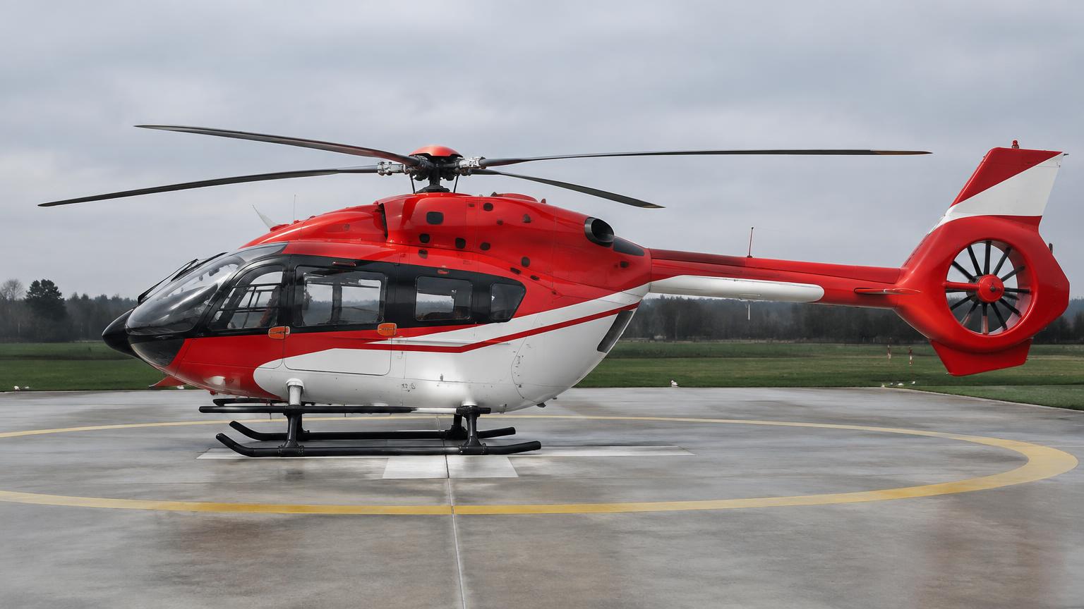
What it looks like
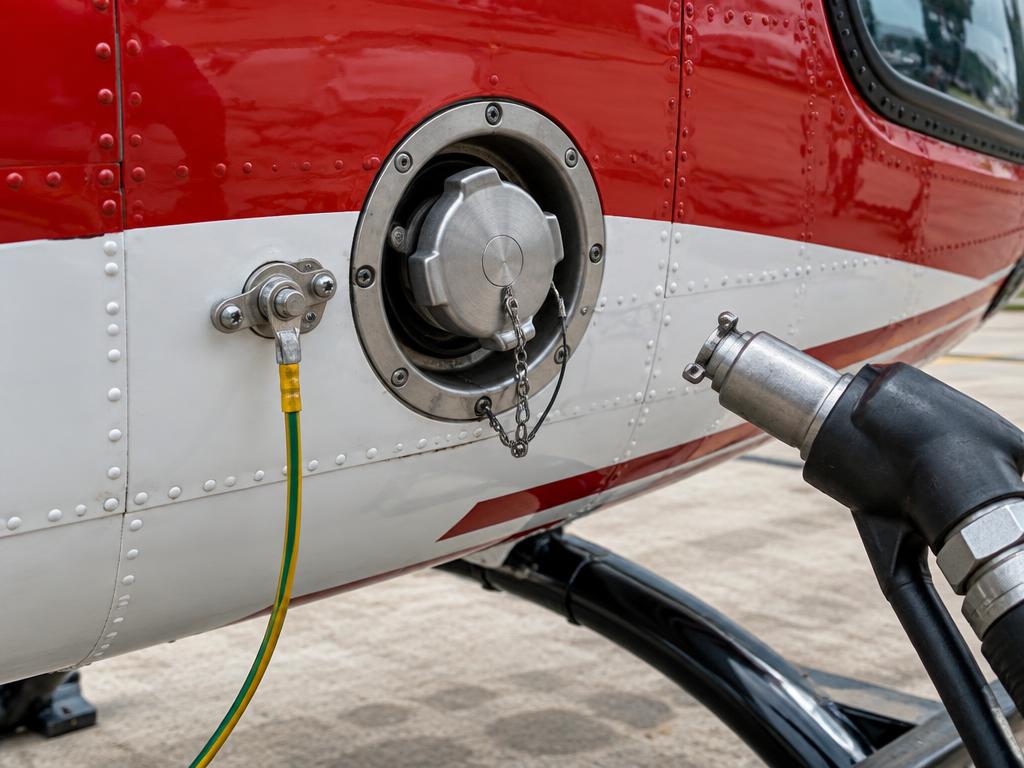
Controls
Boost pump 1
Boost pump 2
Crossfeed valve
Firewall valve 1
Firewall valve 2
Inject failures
What this means
- Normal: each boost pump feeds its own engine, crossfeed closed.
How it works
- A single crashworthy fuel cell under the cabin floor is split into a forward and an aft compartment that are interconnected so the usable fuel behaves as one tank for quantity purposes.
- Each compartment has its own electric boost pump, normally dedicated to one engine, so a pump problem on one side does not automatically affect the other engine.
- The crossfeed valve joins the two feed lines. Opened, either boost pump can supply both engines; closed, each side is isolated.
- Each engine has its own firewall shutoff valve as the last fuel barrier before the FADEC-controlled fuel control unit (FCU) and the engine itself.
- The FADEC/FCU on each engine meters the actual fuel flow to the gas generator based on torque, NG, NF and TOT demands.
How the parts work together
- In normal operation each boost pump feeds its own engine and the crossfeed stays closed — simple, isolated, redundant.
- If a boost pump fails, the affected engine can still suction-feed at low altitude in many conditions, but the crossfeed valve is opened so the healthy pump positively supplies both engines.
- The firewall valves are the primary means of cutting fuel to an engine for a fire or precautionary shutdown — closing one isolates that engine without affecting the other.
- FADEC on each engine is independent, so a fuel-metering problem on one engine does not propagate to the other through the fuel system.
What each part does
Click a box in the diagram or a part below to highlight it.
EDUCATIONAL USE ONLY. Content is summarised from manufacturer documentation for learning. It is not approved flight or maintenance data. Always use the current, aircraft-specific POH/AFM, FCOM, QRH, AMM and operator procedures.