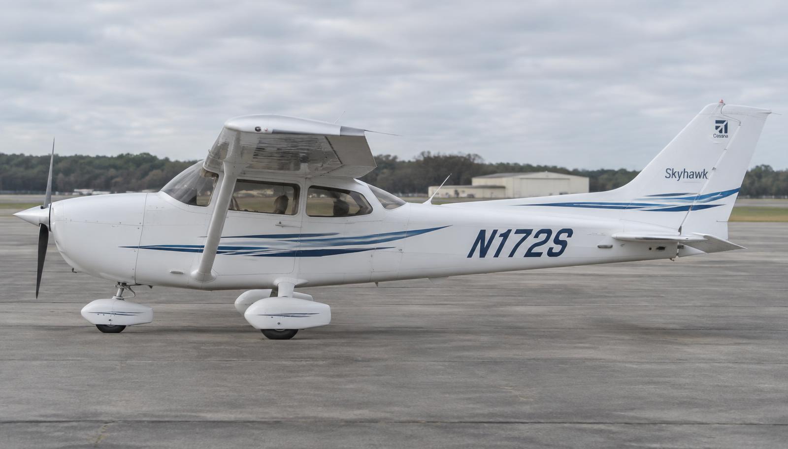
Back to dashboard
Sections menu

Cessna 172S Skyhawk · Components

Components by ATA chapter

Every ATA chapter has its own components page. Pick a chapter, then a part: what it is made of, how it works, what it connects to, the numbers that matter, how it fails and how mechanics inspect it.

Unverified — check your manualText on this page is written from general knowledge. Figures marked ✓ are checked against official FAA/EASA data.See verified data

ATA 21 · Heating & Ventilation

ATA 21 Air Conditioning & Pressurization

Exhaust heat muff & cabin heat valve

A sheet-metal shroud that captures ram air, heats it on the hot muffler surface and delivers it through a push-pull valve to the cabin and windshield defrost outlets.

Location: Shroud around the exhaust muffler; valve on the firewall behind the CABIN HT knob.
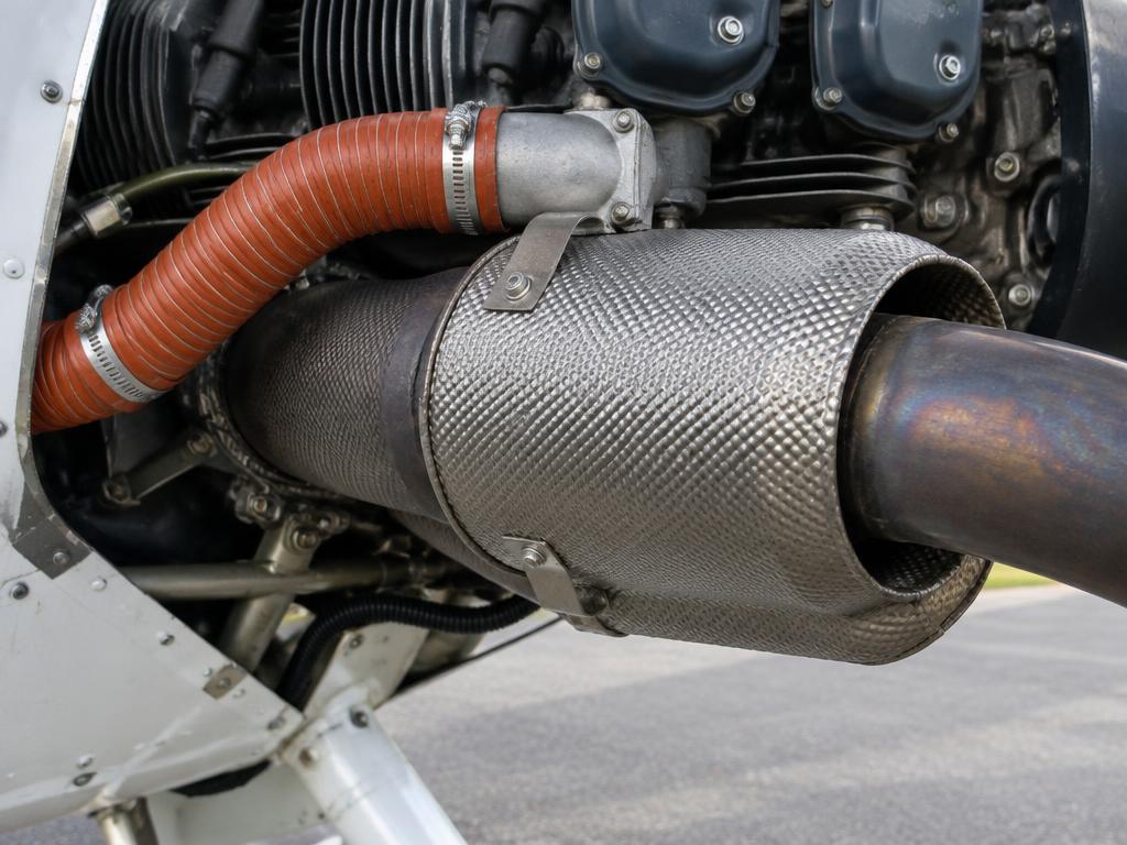
Exhaust heat muff & cabin heat valve on the Cessna 172S Skyhawk
Exhaust heat muff & cabin heat valve · illustrative image

Where it is

Location of Exhaust heat muff & cabin heat valve
Exhaust heat muff & cabin heat valve

How it works

Ram air from a baffle inlet on the engine cowl is ducted into the heat muff, a stainless shroud wrapped around the muffler with internal fins or studs to increase surface area.

Heat transfers by conduction and convection only — exhaust gas and cabin air never mix unless the muffler is cracked.

The CABIN HT knob moves a flapper valve on the firewall: closed, heated air is dumped overboard; open, it flows through SCAT ducting to floor outlets and the defrost nozzles. CABIN AIR mixes in fresh outside air to control temperature.

Construction

  • Stainless steel (321 series) muffler with internal baffle cones.
  • Riveted or clamped heat shroud; SCAT/SCEET flexible ducting rated for high temperature.
  • Firewall valve: aluminium flapper with a cable from the panel knob.

Interfaces with other systems

  • Exhaust system (ATA 78) — the muffler is the heat source.
  • Firewall seals (ATA 54) — any gap admits engine compartment gases.
  • CO detector (if installed).

Technical data

Heat sourceMuffler skin temperature, several hundred °C
ControlPush-pull cable, CABIN HT / CABIN AIR
Muffler inspectionEvery 100 h / annual (AD-driven on some models)

Failure modes

Cracked mufflerCarbon monoxide enters the cabin — headache, drowsiness. Close CABIN HT, open vents, land.
Torn SCAT ductReduced heat, hot air in the engine bay.
Seized flapperHeat stuck on or off.

Inspection

  • Remove the shroud and inspect the muffler for cracks, bulges and burnt-through spots; pressure test if required.
  • Check ducts for chafe and clamp security.
  • Verify valve travel and cable friction.
  • Functional test with a CO detector in the cabin.

Note

Carbon monoxide is odourless — a cheap panel CO detector is strongly recommended.

Pull CABIN HT closed during any engine fire procedure to keep smoke out of the cabin.

Educational summary — verify against the component maintenance manual (CMM) and AMM.

All parts in ATA 21

1.Muffler heat shroud

Sheet-metal jacket around the muffler; ram air passes between shroud and muffler and is heated.

A sheet-metal jacket wrapped around the Lycoming IO-360's exhaust muffler, mounted low on the engine beneath the cowling. It forms the hot-air source for cabin heat and carburetor/induction warmth is not used here since the IO-360 is fuel injected, but cabin heat relies entirely on this shroud.

How it works
  • Ram air enters the shroud through an inlet duct and flows through the annular gap between the muffler outer wall and the shroud, picking up heat by convection from the muffler surface.
  • The heated air is ducted forward through flexible SCAT hose to the firewall heater valve.
  • Because the air only contacts the outside of the muffler, an exhaust leak inside the muffler can push carbon monoxide into the cabin air supply, which is why shroud integrity is safety-critical.
LocationExhaust muffler, engine compartment
Heated air tempApprox. 150-200 F at outlet in cruise
Duct materialAluminized steel shroud, SCAT hose ducting
Failures
  • Muffler internal crack: CO can enter cabin heat air; crew smells exhaust or gets CO detector alert, must shut off cabin heat immediately
  • Shroud corrosion/dents: Reduced heat output, slow cabin warm-up
Inspection
  • Annual inspection for muffler cracks, pinholes, and shroud security per AD-driven exhaust inspection

2.Heater valve (firewall)

Flapper valve on the firewall controlled by the CABIN HT knob.

A flapper-type valve mounted on the firewall of the Cessna 172S, at the point where the heated-air duct from the muffler shroud passes into the cabin.

How it works
  • The CABIN HT knob on the instrument panel is connected by a Bowden (push-pull) cable to the valve flapper.
  • Pulling the knob rotates the flapper open, allowing heated shroud air to flow into the cabin distribution ducts; pushing it in closes the flapper and routes air overboard or shuts flow.
  • The valve has no electrical or pneumatic actuation, it is a simple mechanical cable-operated flap, so cable fraying or disconnection is the main failure path.
LocationFirewall, behind instrument panel
ActuationManual cable, CABIN HT knob
TravelFull open to full closed, no intermediate detents on early models
Failures
  • Cable binding or disconnect: Knob moves but no heat change, or valve stuck full open/closed
  • Valve flapper seal wear: Heat always partially on even with knob closed, unwanted warm air in cabin
Inspection
  • Verify full and free valve travel with knob actuation during annual inspection

3.Cabin air valve

Mixes outside ram air with heated air, controlled by CABIN AIR.

A mixing valve in the Cessna 172S cabin air distribution system that blends unheated ram outside air with the heated air from the firewall heater valve, controlled from the panel by the CABIN AIR knob.

How it works
  • Outside ram air enters through a NACA-style inlet and is ducted to this valve independent of the heater circuit.
  • The CABIN AIR knob, via cable, opens or closes the mixing valve to proportion cold ram air into the cabin vents and defrost outlets.
  • Combined with the heater valve position, the pilot can tailor cabin temperature by blending hot and cold air streams rather than through any thermostatic control.
LocationFirewall/cabin air distribution manifold
ControlCABIN AIR panel knob, cable actuated
FunctionCold air mixing, no heating element itself
Failures
  • Cable seizure: Cabin air temperature cannot be adjusted, stuck hot or cold
Inspection
  • Lubricate and check cable travel at annual inspection

4.Wing-root vents

Adjustable 'eyeball' ram-air vents fed from wing leading-edge inlets.

Adjustable 'eyeball' style ram-air vents located at the wing root of each wing, just outboard of the cabin on the Cessna 172S, feeding fresh outside air directly to each front-seat occupant.

How it works
  • Ram air is captured by small leading-edge wing inlets and ducted inboard through flexible hose to the eyeball vent in the cabin sidewall.
  • Each vent can be rotated to direct airflow and has a shutoff feature by twisting the ball closed.
  • Airflow rate depends entirely on aircraft forward speed and inlet ram pressure, there is no fan assistance.
LocationWing root, cabin sidewall at shoulder height
Flow sourceWing leading-edge ram air inlet
ControlRotating eyeball vent, open/shut twist
Failures
  • Duct hose cracking: Reduced or no airflow to vent despite being open
  • Vent ball seized: Cannot close vent, unwanted draft in cabin
Inspection
  • Inspect duct hoses for cracks and vent ball for free rotation during annual

EDUCATIONAL USE ONLY. Content is summarised from manufacturer documentation for learning. It is not approved flight or maintenance data. Always use the current, aircraft-specific POH/AFM, FCOM, QRH, AMM and operator procedures.