Back to dashboard
Sections menu

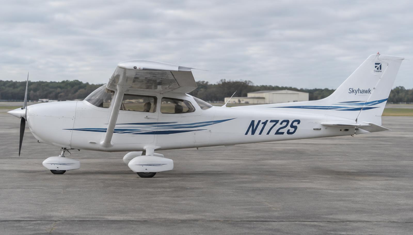
Cessna 172S Skyhawk · Maintenance

Maintenance & fault isolation

Inspection programme by ATA chapter and step-by-step troubleshooting trees, in the style of an AMM / FIM.

Unverified — check your manualText on this page is written from general knowledge. Figures marked ✓ are checked against official FAA/EASA data.See verified data

Inspection programme

WhereIntervalATATaskReference
Fuselage
Each flight05Pre-flight inspection per POH Section 4; fuel sump samplesPOH Sec. 4
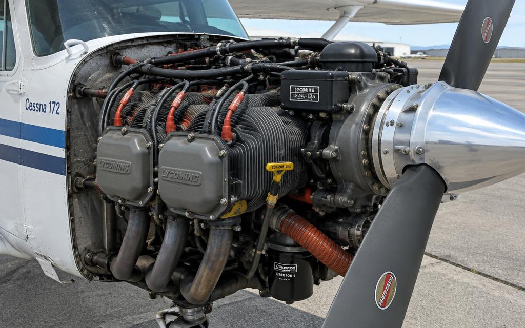
Lycoming IO-360 with cowling open — cylinders, ignition leads, oil dipstick, propeller hub
50 hr79Engine oil and filter change (recommended), screen inspectionLycoming SI 1014
Fuselage
100 hr / Annual05Full inspection to Part 43 App. D scope incl. compression test, magneto timing, control cable tensionC172 MM Ch. 5; 14 CFR 91.409
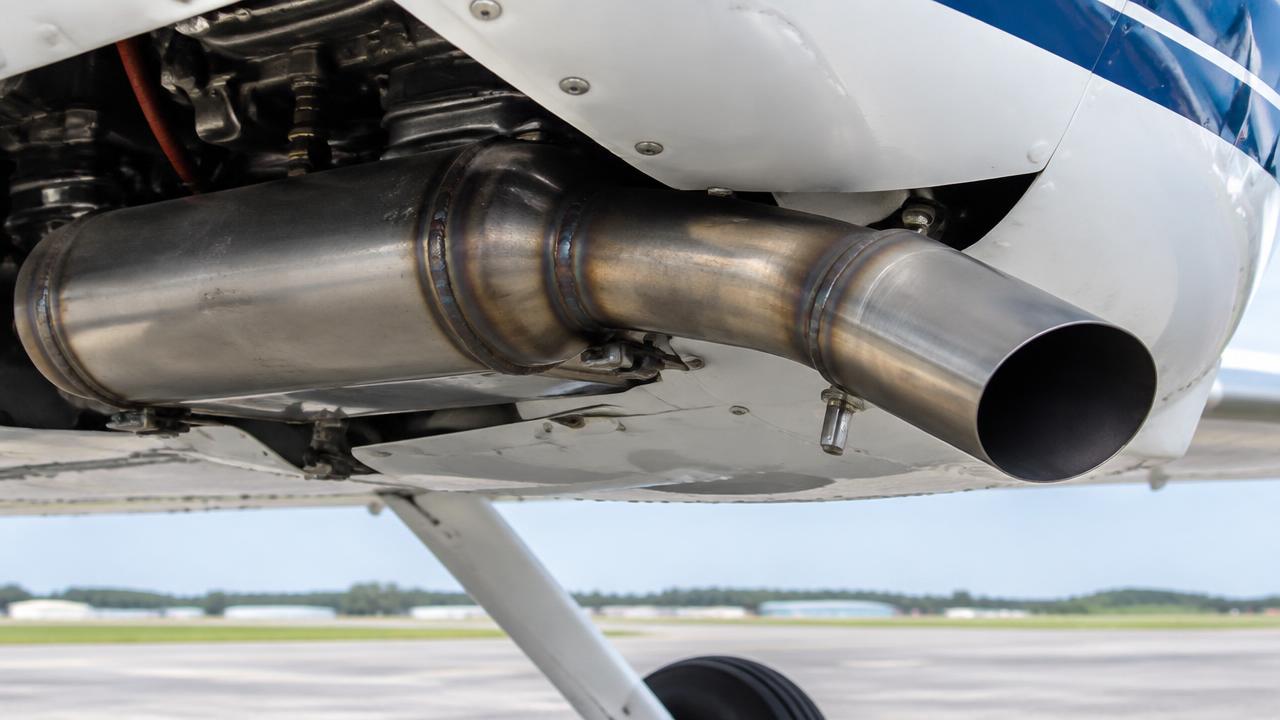
Exhaust muffler and tailpipe below the cowling
100 hr78Muffler / heater shroud inspection for cracks and CO leakageC172 MM Ch. 78
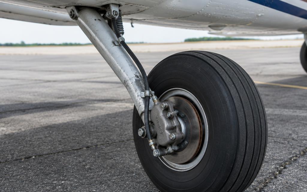
Spring-steel main gear leg, wheel and single-disc brake caliper
100 hr32Brake linings, wheel bearings, nose strut extension and shimmy damperC172 MM Ch. 32
Lycoming IO-360 with cowling open — cylinders, ignition leads, oil dipstick, propeller hub
500 hr74Magneto internal inspection (500-hr inspection)Slick/Bendix SB
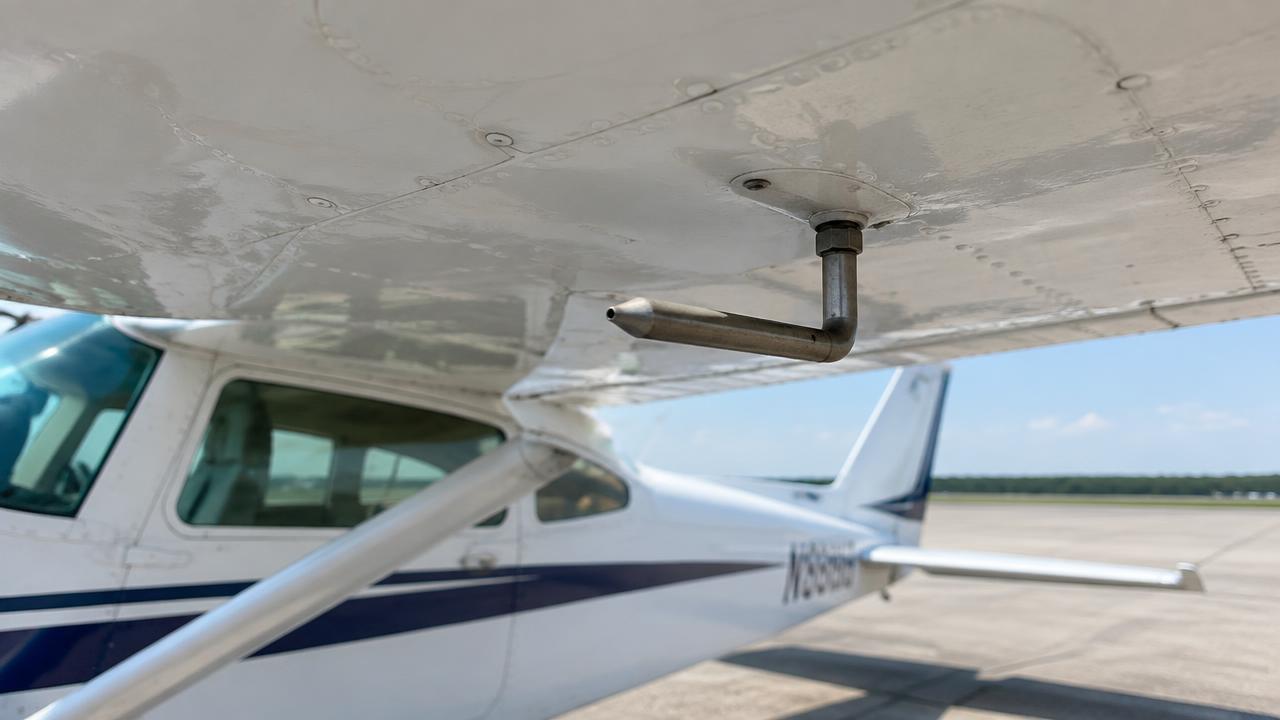
Heated pitot tube under the left wing
24 months34Altimeter, static system and transponder checks (IFR)14 CFR 91.411 / 91.413
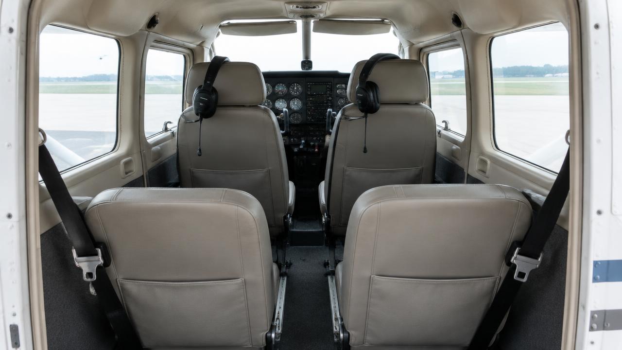
Four-seat cabin with harnesses and headsets
Annual25ELT battery and function, inspection14 CFR 91.207
Lycoming IO-360 with cowling open — cylinders, ignition leads, oil dipstick, propeller hub
2,000 hr / 12 yr72Engine TBO (IO-360-L2A)Lycoming SI 1009
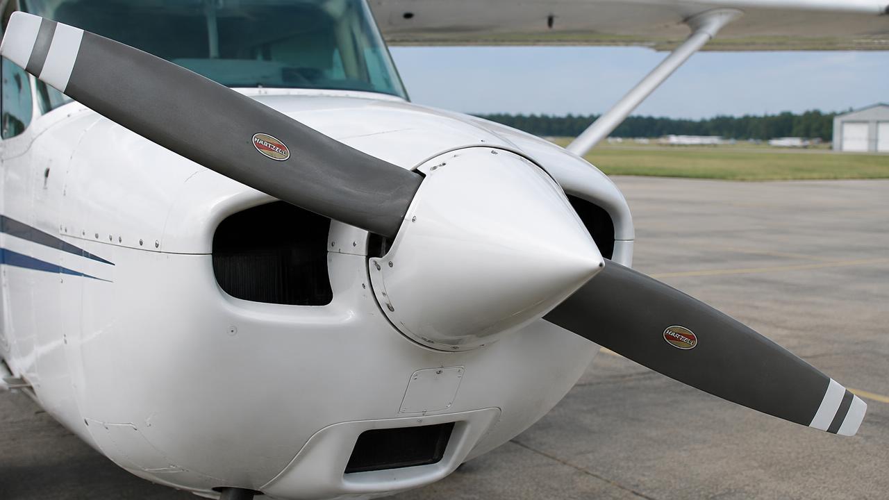
Two-blade fixed-pitch metal propeller and spinner
6 yr / 2,400 hr61Propeller overhaul (fixed pitch: per manufacturer)McCauley SB

Task cards

Step-by-step maintenance tasks with access, tools, limits and warnings — in the style of an AMM task card.

Exhaust muffler & heat muff inspection

ATA 21 · 100 h / annual

Access · Lower cowl, heat shroud removed

Tools & materials · Inspection mirror · Flashlight · Pressure test kit (optional)

Warning · A cracked muffler can fill the cabin with carbon monoxide.

  1. 1.Remove the heat shroud.
  2. 2.Inspect the muffler for cracks, bulges, burned spots, especially around welds and the inner baffles.
  3. 3.Pressure test or immerse test if any doubt.
  4. 4.Inspect the SCAT ducts and heat valve.
  5. 5.Reinstall shroud; run with CABIN HEAT on and check with a CO detector.
CracksNone allowed — replace or repair per AD/SB

Ref: Cessna SEB / AD for exhaust systems
Main battery inspection & service

ATA 24 · 100 h / annual

Access · Battery box (firewall / tailcone per serial)

Tools & materials · Digital multimeter · Hydrometer or capacity tester · Baking soda solution · Terminal brush · Torque wrench

Warning · Batteries emit hydrogen — no sparks or flames. Wear eye protection when handling acid.

  1. 1.Master OFF, STBY BATT OFF; disconnect the negative cable first, then positive.
  2. 2.Remove the battery and inspect the box for corrosion; neutralise any acid with baking soda solution and repaint.
  3. 3.Check the box drain and vent tubes are clear.
  4. 4.Flooded battery: check electrolyte level above plates and specific gravity (approx. 1.260–1.280 charged). Sealed: run capacity test.
  5. 5.Clean terminals; reinstall positive first, negative last; torque; apply corrosion inhibitor.
  6. 6.Power on and check bus voltage on the G1000 (approx. 24–25 V battery only, 28 V with engine running).
Capacity replace below80 % of rated
Open-circuit voltage (charged)approx. 25.5 V

Ref: Cessna 172 MM Ch. 24 / battery CMM

Alternator belt tension check

ATA 24 · 100 h / annual

Access · Upper and lower cowling

Tools & materials · Belt tension gauge or torque wrench · Straightedge

  1. 1.Inspect the belt for cracks, glazing, fraying.
  2. 2.Measure tension per method (deflection or slip torque at the alternator pulley nut).
  3. 3.Adjust by loosening the adjusting arm bolt and moving the alternator; torque the bolts.
  4. 4.New belts: recheck after 10 h run-in.
New belt slip torque (typical)approx. 11–13 ft-lb
Used beltapprox. 7–9 ft-lb

Ref: Lycoming SI 1129 / Cessna MM Ch. 24

Fuel strainer & sump inspection

ATA 28 · 100 h / annual (drain each preflight)

Access · Lower cowl, wing root fairings

Tools & materials · Fuel sampler · Safety wire · New O-ring

Warning · Fire hazard — no smoking, ground the aircraft.

  1. 1.Fuel shutoff OFF. Remove the strainer bowl, clean the screen in solvent.
  2. 2.Install a new O-ring, reinstall bowl, torque and safety-wire.
  3. 3.Fuel shutoff ON, check for leaks with fuel pump ON.
  4. 4.Drain all 13 sumps and check for water and debris.
Fuel grade100LL / 100

Ref: Cessna 172 MM Ch. 28

Brake lining replacement & bleeding

ATA 32 · On condition

Access · Aircraft on jacks or wheel raised

Tools & materials · Rivet tool for linings · Pressure bleeder pot · MIL-PRF-5606 fluid

  1. 1.Remove back plate bolts and slide the caliper off the disc.
  2. 2.Replace worn linings with the riveting tool.
  3. 3.Reinstall; torque bolts and safety.
  4. 4.Bleed from the bottom up: pressure pot to the caliper bleeder, fluid flows up to the reservoir until no bubbles.
  5. 5.Condition new linings with several medium-speed taxi stops.
Minimum lining thicknessapprox. 0.10 in

Ref: Cessna MM Ch. 32 / Cleveland Wheels & Brakes manual

Differential compression test

ATA 72 · 100 h / annual

Access · Upper cowling, all top plugs removed

Tools & materials · Differential compression tester with master orifice · 80 psi regulated air

Warning · Hold the propeller firmly — 80 psi will rotate it violently if not exactly at TDC.

  1. 1.Test with the engine warm.
  2. 2.Bring each cylinder to TDC on compression; apply 80 psi.
  3. 3.Read the cylinder gauge; listen for leakage: oil filler = rings, exhaust = exhaust valve, intake = intake valve.
  4. 4.Compare with the master orifice calibration reading (lowest acceptable value).
  5. 5.Borescope any low cylinder before deciding on removal.
Minimum acceptablemaster orifice value (approx. 40–50/80 typical)

Ref: Lycoming SI 1191A / AC 43.13-1B

Magneto timing check

ATA 74 · 100 h / annual

Access · Upper cowling, spark plug access

Tools & materials · Timing light / buzz box · TDC indicator · Degree wheel

  1. 1.Remove the top spark plug from No. 1 cylinder.
  2. 2.Rotate the propeller in normal direction until No. 1 reaches top dead centre on the compression stroke.
  3. 3.Back up past 25° BTDC and come forward to the timing mark (25° BTDC for IO-360-L2A).
  4. 4.Connect the timing light to each magneto's P-lead terminal and ground; the light should change as the points open exactly at the mark.
  5. 5.Adjust by loosening the mounting clamp and rotating the magneto.
  6. 6.Check internal timing ('E-gap') if within the overhaul interval guidance.
Ignition timing25° BTDC both mags
Mag drop at run-upmax 150 RPM, max 50 RPM difference

Ref: Lycoming Operator's Manual / Slick or Bendix magneto manual

Spark plug removal, cleaning & rotation

ATA 74 · 100 h / annual

Access · Upper/lower cowling

Tools & materials · Deep socket 7/8 in · Gap gauge · Plug cleaner · Torque wrench · Anti-seize compound

  1. 1.Remove plugs in order and place them in a numbered tray (position tells you about each cylinder).
  2. 2.Inspect electrodes: grey-tan normal, black sooty = rich, oily = ring/valve issue, lead fouling = leaning practice.
  3. 3.Clean, gap and test plugs.
  4. 4.Rotate: top to bottom and swap sides (reduces electrode erosion due to polarity).
  5. 5.Install with new gaskets, anti-seize on threads (not first 2), torque.
Torque (typical 18 mm)approx. 35 ft-lb
Electrode gapper plug type, approx. 0.016–0.021 in

Ref: Champion AV6-R / Lycoming SI 1042

Engine oil & filter change

ATA 79 · 50 h (filter) / 4 months

Access · Upper cowling removed

Tools & materials · Oil drain hose / quick drain · Filter wrench · Torque wrench · Filter cutter · Safety wire pliers & 0.032 in wire

Warning · Hot oil causes burns. Treat the propeller as live.

  1. 1.Run the engine to operating temperature so contaminants are suspended.
  2. 2.Shut down, master OFF, mags OFF, key removed. Chock wheels.
  3. 3.Drain oil through the quick-drain valve into a container.
  4. 4.Remove the safety wire and spin-on filter. Cut the filter open and inspect the pleats for metal.
  5. 5.Lubricate the new filter gasket with clean oil, install hand-tight then to specified torque; safety-wire it.
  6. 6.Refill with the approved grade (e.g. 15W-50 or SAE 50 ashless dispersant) to 6–8 qt.
  7. 7.Ground run; check for leaks and normal oil pressure within 30 s.
  8. 8.Record the change in the engine logbook.
Oil filter torqueapprox. 16–18 ft-lb
Capacity8 qt sump
Minimum for flightapprox. 5 qt

Ref: Lycoming SI 1014 / Cessna MM Ch. 12

Fault isolation trees

ATA 73/74

Rough running engine

Engine runs rough in flight or during run-up

Where it is

Location of Rough running engine
Rough running engine

What it looks like

Lycoming IO-360 with cowling open — cylinders, ignition leads, oil dipstick, propeller hub
Lycoming IO-360 with cowling open — cylinders, ignition leads, oil dipstick, propeller hub · illustrative image

Is the roughness present on one magneto only during the mag check?

Ref: POH Sec. 3; Lycoming Operator's Manual troubleshooting

ATA 24

Low voltage annunciation

LOW VOLTS light or ammeter discharge

Where it is

Location of Low voltage annunciation
Low voltage annunciation

What it looks like

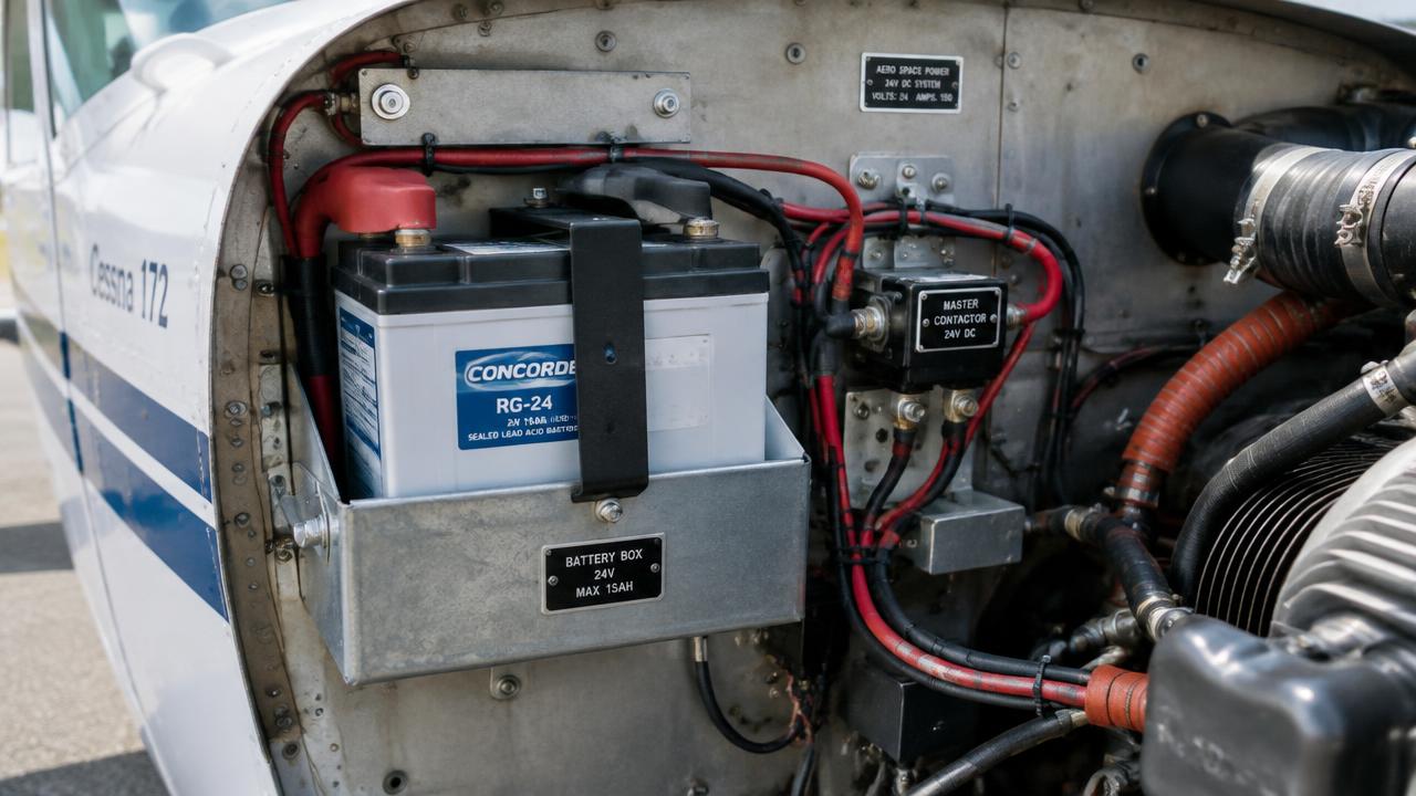
24 V battery box and master contactor on the firewall
24 V battery box and master contactor on the firewall · illustrative image

Is the ALT FIELD circuit breaker popped?

Ref: POH Sec. 3 Electrical Power Supply Malfunctions

EDUCATIONAL USE ONLY. Content is summarised from manufacturer documentation for learning. It is not approved flight or maintenance data. Always use the current, aircraft-specific POH/AFM, FCOM, QRH, AMM and operator procedures.