Back to dashboard
Sections menu

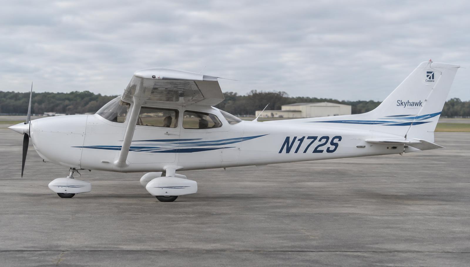
Cessna 172S Skyhawk · Interactive POH

Full manual

Organised like the official Pilot's Operating Handbook with maintenance by ATA chapter. Search across every section.

Unverified — check your manualText on this page is written from general knowledge. Figures marked ✓ are checked against official FAA/EASA data.See verified data
1

General

EngineLycoming IO-360-L2A, 180 HP
Max takeoff weight2,550 lb
Cruise (75%)~124 KTAS
Fuel capacity56 gal (53 usable)
Vno / Vne129 / 163 KIAS
Best glide68 KIAS

Model applicability

  • 172S Skyhawk SP — G1000 — 2005 – present · S/N 172S9491 and on (G1000 installs; verify on data plate)
  • 172S Skyhawk SP — analog — 1998 – 2004 · S/N 172S8001 – approx. 172S9490
  • 172R Skyhawk — 1996 – present (limited) · S/N 17280001 and on
  • 172N Skyhawk (carbureted) — 1977 – 1980 · S/N approx. 17267585 – 17274009
2

Limitations

Airspeed (KIAS)

Vne — never exceed✓ FAA163
Vno — max structural cruising✓ FAA129
Va — maneuvering @ 2550 / 2200 / 1900 lb105 / 98 / 90
Vfe — flaps 10°110
Vfe — flaps 10°–30°85
Max demonstrated crosswind15 kt

Powerplant

Max RPM2700
Oil temperature max245 °F
Oil pressure min / normal / max20 / 50–90 / 115 PSI
Fuel grade100LL (blue) or 100 (green)

Weight & load factor

Max takeoff (normal)✓ FAA2550 lb
Max takeoff (utility)✓ FAA2200 lb
Load factor flaps up (normal)+3.8 / −1.52 g
Load factor flaps down+3.0 g
3

Emergency Procedures

Engine Failure Immediately After Takeoff

Airspeed70 KIAS flaps UP / 65 KIAS flaps DOWN
MixtureIDLE CUTOFF
Fuel shutoff valveOFF (push full in)
MagnetosOFF
Wing flapsAS REQUIRED
Standby batteryOFF
Master switchOFF (when flaps no longer needed)
Cabin doorUNLATCH
LandSTRAIGHT AHEAD

Do not attempt to turn back to the runway at low altitude.

Engine Failure During Flight (Restart)

Airspeed68 KIAS (best glide)
Fuel shutoff valveON
Fuel selectorBOTH
Fuel pumpON
MixtureRICH (if restart has not occurred)
MagnetosBOTH (or START if prop stopped)
Fuel pumpOFF after restart

Engine Fire In Flight

MixtureIDLE CUTOFF
Fuel shutoff valveOFF
Fuel pumpOFF
Master switchOFF
Cabin ventsOPEN (as needed)
Cabin heat & airOFF
Airspeed100 KIAS (increase to find speed that extinguishes fire)
Forced landingEXECUTE

Electrical Fire In Flight

Standby batteryOFF
Master switchOFF
Vents / cabin air / heatCLOSED
Fire extinguisherACTIVATE
Avionics switchOFF
All other switchesOFF (except magnetos)
VentsOPEN after fire out
4

Normal Procedures

Expanded, step-by-step versions with explanations: open the interactive procedures →

Before Starting Engine (amplified)

  1. 1. Preflight inspection — COMPLETE
    Every start begins with a completed walkaround — fuel sumped, oil checked, controls free.
  2. 2. Passenger briefing — COMPLETE
    Covers seat belts, doors, emergency exits and sterile-cockpit expectations.
  3. 3. Seats & seat belts — ADJUST & LOCK
    Seat rail pin must engage — an unlocked seat sliding back on takeoff has caused loss of control (see AD on seat rails).
  4. 4. Brakes — TEST & SET
    Firm pedals confirm hydraulic brake pressure before the propeller turns.
  5. 5. Electrical equipment — OFF
    Avoids loading the battery and protects avionics from start voltage transients.
  6. 6. AVIONICS switch (BUS 1 & 2) — OFF
    Starter-motor voltage drop and spikes can damage avionics.
  7. 7. Fuel selector valve — BOTH
    Feeds from both wing tanks by gravity — the standard setting for takeoff and landing.
  8. 8. Fuel shutoff valve — ON (push full in)
    The red shutoff knob must be fully in; partly out restricts fuel flow.

Starting Engine (with battery) (amplified)

  1. 1. Throttle — OPEN ¼ INCH
    Provides enough airflow for the engine to catch without over-revving after start.
  2. 2. Mixture — IDLE CUTOFF
    Prevents fuel flowing to the cylinders until you deliberately prime.
  3. 3. STBY BATT switch — TEST (10 s), then ARM
    Test confirms the standby battery holds the essential bus; ARM lets it take over automatically if the main bus fails.
  4. 4. Engine indicating system — CHECK parameters (no red X)
    Confirms the engine display is alive before the start so you can watch oil pressure rise.
  5. 5. MASTER switch (ALT & BAT) — ON
    Powers the starter, fuel pump and instruments.
  6. 6. Propeller area — CLEAR
    Shout "CLEAR PROP" and visually confirm no one is near the propeller.
  7. 7. BEACON light — ON
    Signals to ground crew that the engine is about to start.
  8. 8. FUEL PUMP switch — ON
    Pressurises the fuel system for priming.
  9. 9. Mixture — FULL RICH for 3–5 s, then IDLE CUTOFF
    This is how the injected engine is primed — less time when the engine is warm.
  10. 10. FUEL PUMP switch — OFF
    Pump is not needed once primed; leaving it on can flood the engine.
  11. 11. MAGNETOS switch — START (release when engine starts)
    Engages the starter; releasing returns the key to BOTH so both magnetos fire.
  12. 12. Mixture — ADVANCE smoothly to RICH when engine starts
    The engine runs on residual prime only for a second — advance mixture as it fires.
  13. 13. Oil pressure — CHECK — green within 30 s
    No oil pressure within 30 s (60 s in cold weather) = shut down immediately to prevent engine damage.
  14. 14. Ammeters / volts — CHECK (alternator charging)
    Confirms the alternator is online and recharging the battery after the start.
  15. 15. NAV lights — ON as required
    Required between sunset and sunrise.
  16. 16. AVIONICS switch (BUS 1 & 2) — ON
    Safe to power avionics now that start transients are over.

Before Takeoff — Engine Run-up (amplified)

  1. 1. Parking brake — SET
    Prevents creeping forward during high-RPM run-up.
  2. 2. Flight controls — FREE & CORRECT
    Watch ailerons and elevator move the right way — gust lock removed.
  3. 3. Flight instruments — CHECK (PFD & standby)
    Altimeter set to field elevation, attitude erect, heading agrees with compass.
  4. 4. Fuel selector — BOTH
    Confirm before takeoff.
  5. 5. Mixture — RICH (or leaned for density altitude above 3000 ft)
    Too rich at high density altitude loses power; lean for max RPM.
  6. 6. Elevator trim — SET FOR TAKEOFF
    Wrong trim gives excessive or insufficient pitch force at rotation.
  7. 7. Throttle — 1800 RPM
    Standard run-up RPM.
  8. 8. Magnetos — CHECK — L, BOTH, R, BOTH
    Max drop 150 RPM per side, max 50 RPM difference. No drop = possible hot magneto (switch not grounding).
  9. 9. Vacuum / engine & electrical indications — CHECK
    Volts, amps, oil temp and pressure all in the green.
  10. 10. Throttle — CHECK IDLE, then 1000 RPM or less
    Confirms the engine won't quit at idle on landing.
  11. 11. Wing flaps — UP – 10°
    0–10° for normal takeoff, 10° for short-field.
  12. 12. Cabin doors & windows — CLOSED & LOCKED
    An open door in flight is noisy but not dangerous — still, fix it on the ground.

Securing Airplane (Shutdown) (amplified)

  1. 1. Parking brake — SET
    Holds the aircraft while you shut down.
  2. 2. Throttle — IDLE
    Cools the engine briefly before cutoff.
  3. 3. AVIONICS switch — OFF
    Protects avionics from the voltage drop at shutdown.
  4. 4. Electrical equipment — OFF
    Reduces load before master off.
  5. 5. Mixture — IDLE CUTOFF (pulled full out)
    Starves the engine of fuel so it stops cleanly without dieseling.
  6. 6. MAGNETOS switch — OFF
    Grounds the magnetos — a live (ungrounded) magneto makes the propeller dangerous.
  7. 7. MASTER switch (ALT & BAT) — OFF
    Prevents the battery draining.
  8. 8. STBY BATT switch — OFF
    Otherwise the standby battery discharges.
  9. 9. Control lock — INSTALL
    Protects control surfaces from wind damage.
  10. 10. Fuel selector valve — LEFT or RIGHT
    Prevents cross-feeding between tanks when parked on a slope.

Normal Takeoff & Climb (amplified)

  1. 1. Wing flaps — 0°–10°
    Normal takeoff uses 0°; 10° shortens ground roll slightly.
  2. 2. Mixture — RICH (or leaned above 3,000 ft DA)
    Full power needs correct mixture; at high density altitude lean for max RPM.
  3. 3. Throttle — FULL OPEN, smoothly
    Smooth application avoids stumbling and directional swings.
  4. 4. Engine instruments & airspeed — CHECK — RPM green, oil pressure green, airspeed alive
    Abort early if anything is wrong; static RPM below the POH range means power loss.
  5. 5. Elevator control — LIFT NOSEWHEEL at 55 KIAS
    Rotation speed — the aircraft flies off at about 60 KIAS.
  6. 6. Climb speed — 70–80 KIAS (Vy approx. 74)
    Vy gives best rate of climb; Vx (approx. 62) for obstacles.
  7. 7. Flaps — RETRACT at safe altitude
    Removes drag once clear of obstacles.
  8. 8. Elevator trim — SET for climb speed
    Reduces workload.
  9. 9. FUEL PUMP — OFF above 1,000 ft AGL (if used)
    Pump not needed once established.

Normal Approach & Landing (amplified)

  1. 1. Fuel selector — BOTH
    Gravity feed from both tanks for landing.
  2. 2. Mixture — RICH
    Full power may be needed for a go-around.
  3. 3. Airspeed — 65–75 KIAS flaps up
    Approach speed before flap extension.
  4. 4. Flaps — AS DESIRED (0°–10° below 110 KIAS, 10°–30° below 85 KIAS)
    Flap speed limits protect the structure.
  5. 5. Airspeed — 60–70 KIAS flaps 30°
    Final approach speed; adjust for gusts.
  6. 6. Elevator trim — ADJUST
    Stabilised approach.
  7. 7. Throttle — IDLE over threshold
    Allow the aircraft to settle.
  8. 8. Touchdown — MAIN WHEELS FIRST
    Nosewheel is not designed for landing loads.
  9. 9. Landing roll — LOWER NOSEWHEEL GENTLY
    Keep weight off the nosewheel.
  10. 10. Braking — MINIMUM REQUIRED
    Saves brakes and tyres.

Engine Failure After Takeoff (amplified)

  1. 1. Airspeed — 70 KIAS (flaps UP) / 65 KIAS (flaps 10–FULL)
    Best glide — lower the nose immediately to keep flying speed.
  2. 2. Mixture — IDLE CUTOFF
    Reduces fire risk on impact.
  3. 3. Fuel shutoff valve — OFF (pull full out)
    Removes fuel supply.
  4. 4. Magnetos — OFF
    Removes ignition sources.
  5. 5. Wing flaps — AS REQUIRED (FULL recommended)
    Lowest touchdown speed.
  6. 6. MASTER switch (ALT & BAT) — OFF (after flaps set)
    Electrical fire prevention; flaps need power so set them first.
  7. 7. Cabin door — UNLATCH
    Ensures exit if the frame distorts.
  8. 8. Land — STRAIGHT AHEAD
    Turning back at low altitude often ends in a stall-spin.

Emergency Landing Without Engine Power (amplified)

  1. 1. Airspeed — 68 KIAS (best glide at max weight)
    Maximises glide distance — approx. 1.5 nm per 1,000 ft.
  2. 2. Field — SELECT — into wind if possible
    Pick early, plan a normal pattern.
  3. 3. Fuel selector — BOTH
    Restart attempt: rule out tank starvation.
  4. 4. FUEL PUMP — ON
    Rules out engine-driven pump failure.
  5. 5. Mixture — RICH
    Restart attempt.
  6. 6. Magnetos — BOTH (START if prop stopped)
    Restart.
  7. 7. Passengers & ATC — BRIEF / 121.5 MHz / transponder 7700
    Get help on its way.
  8. 8. If no restart: secure — MIXTURE CUTOFF, FUEL OFF, MAGS OFF
    Prepare for touchdown.
  9. 9. Flaps — FULL when landing assured
    Slowest touchdown.
  10. 10. MASTER — OFF
    Fire prevention.
  11. 11. Doors — UNLATCH before touchdown
    Exit after impact.

Flight Plan Entry (G1000 FPL) (amplified)

  1. 1. FPL key — PRESS
    Opens the active flight plan page.
  2. 2. Large FMS knob — PUSH to show the cursor
    Lets you enter waypoints.
  3. 3. Departure airport — ENTER ident with small/large knobs, ENT
    First line of the route.
  4. 4. Waypoints / airways — ENTER each fix, ENT (LD AIRWY for an airway)
    Builds the route in order.
  5. 5. Destination — ENTER ident, ENT
    Last waypoint.
  6. 6. PROC key — SELECT departure / arrival / approach as required
    Loads published procedures.
  7. 7. Route check — CHECK distances, tracks and total vs flight plan
    Catches typing errors (wrong waypoint with same name).
  8. 8. CDI — GPS
    Navigation source for following the route.

Autopilot Use (GFC 700) (amplified)

  1. 1. Autopilot preflight test — PFT complete — AFCS annunciation clears
    Runs automatically at power-up; must pass before use.
  2. 2. Trim aircraft — SET in climb
    Engage in trimmed flight to avoid a jolt.
  3. 3. AP key — PRESS (above 800 ft AGL)
    Engages autopilot in pitch (PIT) and roll (ROL) hold by default.
  4. 4. HDG key + HDG bug — SET heading
    Lateral mode: follows heading bug.
  5. 5. NAV key — PRESS (CDI on GPS)
    Couples to the flight plan route.
  6. 6. ALT key / VS / FLC — SELECT vertical mode
    ALT holds altitude; VS a rate; FLC holds airspeed in climb/descent.
  7. 7. Altitude preselect — SET target altitude
    Autopilot captures ALTS when reached.
  8. 8. APR key — PRESS for approach (GPS / LOC / GS)
    Couples the approach after loading and activating.
  9. 9. AP DISC button — PRESS to disconnect
    Red button on the yoke — always ready to hand-fly.

Short-Field Takeoff (amplified)

  1. 1. Wing flaps — 10°
    POH short-field setting for best obstacle clearance.
  2. 2. Brakes — APPLY and HOLD
    Lets the engine reach full power before the roll starts.
  3. 3. Throttle — FULL
    Maximum power for minimum ground roll.
  4. 4. Mixture — RICH (lean for max RPM above 3,000 ft DA)
    Correct mixture gives full power.
  5. 5. Brakes — RELEASE
    Start the takeoff roll.
  6. 6. Elevator — Slightly tail-low attitude
    Reduces nosewheel load.
  7. 7. Climb speed — 56 KIAS until obstacles cleared
    Short-field obstacle-clearance speed in the POH table.
  8. 8. Flaps — RETRACT slowly above 60 KIAS
    Avoid sink when retracting.

Balked Landing (Go-Around) (amplified)

  1. 1. Throttle — FULL
    Maximum power to stop the descent.
  2. 2. Pitch — Climb attitude
    Expect a strong nose-up push — hold it with forward pressure and trim.
  3. 3. Wing flaps — RETRACT to 20°
    30° flaps make too much drag to climb well.
  4. 4. Airspeed — 60 KIAS
    Safe climb speed with flaps 20°.
  5. 5. Wing flaps — 10°, then 0° once safely climbing
    Clean up in stages to avoid sink.
  6. 6. Trim — SET
    Reduces control forces.

Cruise & Leaning (amplified)

  1. 1. Power — 2100–2700 RPM per POH table (max 75%)
    Pick power for desired speed and fuel burn.
  2. 2. Trim — SET for level flight
    Hands-off cruise.
  3. 3. Mixture — LEAN to peak EGT, then richen approx. 50 °F
    Best power / safe engine temperatures (follow the POH method).
  4. 4. Engine page — CHECK oil T&P, CHT, fuel flow
    Spot trends early.
  5. 5. Fuel selector — BOTH
    Feeds from both tanks.
  6. 6. Fuel quantity — Compare with planned burn
    Detects leaks or wrong fuel flow early.

Electrical Fire in Flight (amplified)

  1. 1. STBY BATT — OFF
    Removes standby power from the bus.
  2. 2. MASTER (ALT & BAT) — OFF
    Removes all electrical power — most electrical fires go out.
  3. 3. Vents / cabin air / heat — CLOSED
    Stops airflow feeding the fire.
  4. 4. Fire extinguisher — ACTIVATE if needed
    Halon portable bottle.
  5. 5. AVIONICS — OFF
    Prevents surge when power returns.
  6. 6. If power is needed: MASTER — ON, then breakers in one at a time
    Find and isolate the faulty circuit.

Cabin

Pitot tube coverREMOVE
Required documents (ARROW)ON BOARD
Parking brakeSET
Avionics switchOFF
Master switchON
Fuel quantityCHECK
Low fuel annunciatorsCHECK
FlapsEXTEND
Master switchOFF
Fuel selector valveBOTH

Empennage & Right Wing

Baggage doorCHECK, LOCK
Rudder gust lockREMOVE
Tail tie-downDISCONNECT
Control surfacesCHECK freedom & security
Right flap & aileronCHECK
Right wing tie-downDISCONNECT
Main wheel tireCHECK inflation & condition
Fuel sumps (right)DRAIN & CHECK
Fuel quantityCHECK VISUALLY
Fuel capSECURE & VENT CLEAR

Nose

Fuel strainer drainDRAIN
Engine oil dipstickCHECK (≥5 qt)
Engine cooling inletsCLEAR
Propeller & spinnerCHECK nicks & security
Air filterCHECK
Nose strutCHECK inflation
Static source (left side)CHECK BLOCKAGE

Left Wing

Fuel sumps (left)DRAIN & CHECK
Fuel quantity & capCHECK
Fuel tank ventCHECK BLOCKAGE
Stall warningCHECK
Pitot tubeCHECK clear
Landing/taxi lightsCHECK
Left aileron & flapCHECK

Before Takeoff (Runup)

Parking brakeSET
Flight controlsFREE & CORRECT
Fuel selectorBOTH
Elevator trimTAKEOFF
Throttle1800 RPM
MagnetosCHECK (max drop 150 RPM, 50 RPM diff)
Vacuum / engine instrumentsCHECK
AmmeterCHECK
ThrottleCHECK IDLE, then 1000 RPM
FlapsUP–10°
Doors & windowsCLOSED & LOCKED

Normal Takeoff

Wing flaps0°–10°
ThrottleFULL
MixtureRICH (lean above 3000 ft)
ElevatorLIFT NOSE at 55 KIAS
Climb speed70–80 KIAS
Flaps (if extended)RETRACT at safe altitude

Normal Landing

Airspeed65–75 KIAS (flaps up)
Wing flapsAS DESIRED (below 110 / 85 KIAS)
Airspeed (full flaps)60–70 KIAS
TouchdownMAIN WHEELS FIRST
BrakingMINIMUM REQUIRED
5

Performance

Interactive takeoff/landing and weight & balance calculators are in the Performance & W/B tab.

7

Airplane & Systems Description

Cockpit & Avionics ATA 23, 24, 31, 34

Where it is

Location of Cockpit & Avionics
Cockpit & Avionics

Two-seat-abreast cockpit with either analog 'six-pack' gauges or the Garmin G1000 glass panel.

  • Pitot-static system feeds the airspeed indicator, altimeter and VSI. The pitot tube is on the left wing; static port on the left fuselage side, with an alternate static source inside the cabin.
  • Gyroscopic instruments: attitude indicator and heading indicator are driven by an engine-driven vacuum pump (analog models); turn coordinator is electric for redundancy.
  • G1000 models replace these with AHRS and an air data computer feeding a PFD and MFD.
  • Electrical: 28 V DC system with a 60 A alternator and 24 V battery; split master switch (ALT / BAT).

Lycoming IO-360-L2A & Propeller ATA 61, 71, 72, 73, 74, 79

Where it is

Location of Lycoming IO-360-L2A & Propeller
Lycoming IO-360-L2A & Propeller

What it looks like

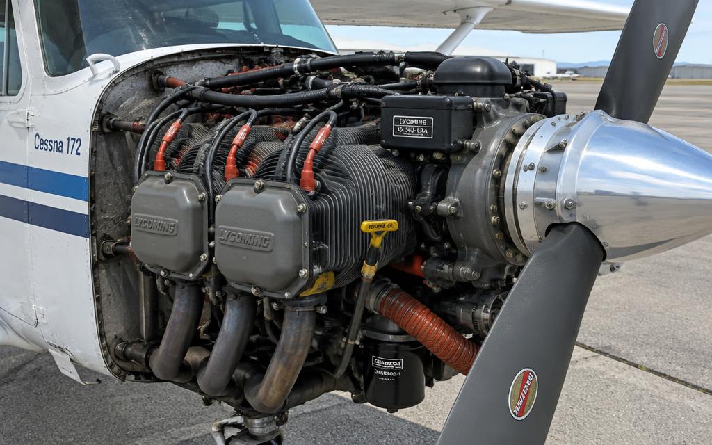
Lycoming IO-360 with cowling open — cylinders, ignition leads, oil dipstick, propeller hub
Lycoming IO-360 with cowling open — cylinders, ignition leads, oil dipstick, propeller hub · illustrative image

Four-cylinder, horizontally opposed, air-cooled, fuel-injected engine driving a fixed-pitch two-blade propeller.

  • Fuel injection meters fuel based on throttle position and mixture setting; the mixture control leans the engine for altitude.
  • Dual magneto ignition: two independent spark plugs per cylinder, powered by engine-driven magnetos — the engine runs even with total electrical failure.
  • Wet-sump lubrication holds 8 qt of oil; an oil cooler and baffling manage temperatures.
  • Fixed-pitch McCauley propeller: RPM is controlled directly by the throttle.

High Wing & Flight Controls ATA 27, 28, 57

Where it is

Location of High Wing & Flight Controls
High Wing & Flight Controls

What it looks like

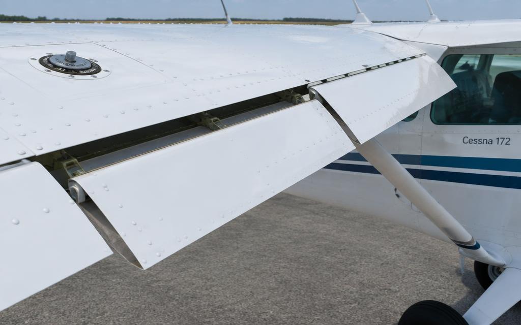
Wing trailing edge — Fowler flap, aileron and fuel filler cap on top
Wing trailing edge — Fowler flap, aileron and fuel filler cap on top · illustrative image

Strut-braced high wing with integral fuel tanks, ailerons, and single-slot electric flaps.

  • Ailerons control roll through cables and bellcranks from the control yoke.
  • Electrically actuated flaps extend to 10°, 20° and 30°; max flap extended speed (Vfe) is 110 KIAS for 10° and 85 KIAS for full.
  • Fuel tanks in each wing feed by gravity through a fuel selector (LEFT/RIGHT/BOTH). The high wing makes gravity feed possible — no fuel pump required for normal feed.
  • A stall warning horn is triggered by a reed in the left leading edge.

Fixed Tricycle Landing Gear ATA 32

Where it is

Location of Fixed Tricycle Landing Gear
Fixed Tricycle Landing Gear

What it looks like

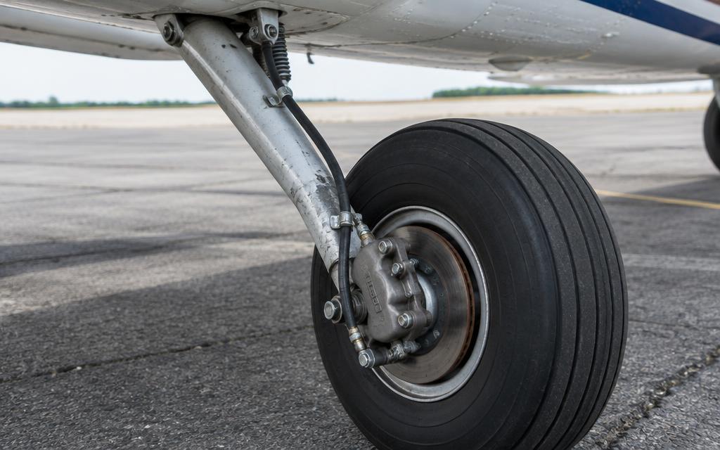
Spring-steel main gear leg, wheel and single-disc brake caliper
Spring-steel main gear leg, wheel and single-disc brake caliper · illustrative image

Fixed tricycle gear with tubular spring-steel main legs and a steerable oleo nose strut.

  • Main gear legs are spring steel and absorb landing loads by flexing.
  • The nose gear uses an air/oil (oleo) shock strut and a shimmy damper, and is steered through the rudder pedals.
  • Toe brakes operate hydraulic single-disc brakes on each main wheel; parking brake handle locks pressure.

Fuselage & Cabin Systems ATA 21, 25, 52, 53, 78

Where it is

Location of Fuselage & Cabin Systems
Fuselage & Cabin Systems

Semi-monocoque all-aluminium fuselage seating four, with cabin heat and ventilation.

  • Semi-monocoque structure: skin carries load together with formers and stringers.
  • Cabin heat comes from a heat shroud around the exhaust muffler — a cracked muffler can introduce carbon monoxide, so a CO detector is recommended.
  • Baggage area aft of rear seats, 120 lb max (Area A).

Empennage ATA 27, 55

Where it is

Location of Empennage
Empennage

What it looks like

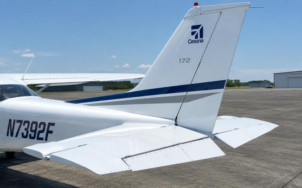
Empennage — fin, rudder, stabilizer and elevator with trim tab
Empennage — fin, rudder, stabilizer and elevator with trim tab · illustrative image

Conventional tail with stabilizer, elevator with trim tab, vertical fin and rudder.

  • Elevator controls pitch via cables from the yoke; a manual trim wheel drives the trim tab.
  • Rudder controls yaw through the rudder pedals, interconnected with nosewheel steering.
  • Rotating beacon on the vertical fin tip.
7A

Annunciators & Fault Messages

Open the interactive fault finder →

OIL PRESSUREOil pressure below 20 PSI.
LOW VOLTSMain bus voltage below ~24.5 V — the alternator is no longer charging; you're running on battery.
HIGH VOLTSBus voltage above ~32 V — the voltage regulator has failed high.
LOW VACUUMVacuum below 3.5 in Hg — gyro attitude and heading indicators will slowly become unreliable.
LOW FUEL L / RFuel in the indicated tank below ~5 gallons.
PITOT HTPitot heat switch is ON but heater current is not detected.
STBY BATTThe standby battery is discharging — it's powering the essential bus.
Rough running engineEngine running rough — not an annunciator but a common in-flight symptom.
Engine fire in flightSmoke or flames from the cowling, usually from a fuel or oil leak hitting the exhaust. The 172 has no fire detection or extinguishing system in the engine bay.
Electrical fire in flightSmell of burning insulation or smoke behind the panel.
Carburettor / induction icing (carb models)Ice forms in the carburettor venturi or throttle plate, restricting airflow. Gradual RPM loss with fixed-pitch prop, possibly rough running.
Inadvertent spinAircraft is stalled and autorotating. The 172 is approved for intentional spins only in the utility category within limits.
Door opens in flightCabin door pops open, usually on takeoff. Noisy but the aircraft flies normally; the door trails open a few inches.
Brake failure on groundToe brake goes soft or to the floor — no braking on that wheel.
Ammeter shows high charge after startLarge positive charge rate after start is normal for a few minutes as the battery recovers; if it stays high the battery may be weak or failing.
Magneto failure / rough on one magEngine rough with one magneto selected; RPM drop exceeds limit.
OIL TEMP highOil temperature in or near the red range (limit approx. 245 °F). Often comes with rising CHT; low oil quantity or a blocked cooler are common.
CHT high on one cylinderOne cylinder head temperature well above the others (limit approx. 500 °F).
Airspeed unreliable (pitot/static blocked)Airspeed reads wrong: a blocked pitot makes it act like an altimeter; a blocked static freezes altimeter and VSI.
LOW VOLTS — alternator failureAlternator offline, battery discharging. Ammeter shows discharge, LOW VOLTS annunciator on.
Inadvertent icing encounterThe 172 is not approved for flight into known icing. Ice on wings, prop and windscreen quickly ruins performance and raises stall speed.
Water in fuel / fuel contaminationWater or debris found in sumps during preflight, or engine coughs and runs rough shortly after takeoff.
7B

Systems In Depth (engine, gear, controls…)

Deep dive · ATA 21

Heating & Ventilation — in depth

Cabin heat

Heat comes from a shroud (heat muff) around the exhaust muffler. Ram air passes between the shroud and the hot muffler, then through the CABIN HEAT valve on the firewall into the cabin outlets at the floor and windscreen defrost.

The CABIN AIR knob mixes fresh outside air with heated air. Pulling CABIN HEAT fully out gives maximum heat.

Carbon monoxide hazard

A crack in the muffler inside the shroud lets exhaust gas into the cabin heat air. CO is odourless; symptoms are headache, drowsiness and impaired judgement.

Annual inspection: remove the shroud and pressure-test or visually inspect the muffler; many operators fit a CO detector on the panel.

Warning · If CO is suspected: CABIN HEAT OFF, all fresh-air vents OPEN, open a window, land as soon as possible.

Ventilation

Fresh air enters via adjustable ventilators in the wing roots (air scoops in the leading edge of the wing root) and the cabin air inlet. There is no air conditioning or pressurisation on a standard 172.

Deep dive · ATA 24

Electrical Power — 28 V DC system in depth

Architecture

The 172S (G1000) uses a 28 V DC, negative-ground, single-alternator system. Power sources are a 60 A belt-driven alternator, a 24 V main battery (lead-acid or sealed) in the engine compartment/aft firewall, and a standby battery that keeps the primary flight display and essential bus alive if the main system fails.

Distribution is through two primary buses (Electrical Bus 1 and 2), two avionics buses fed via the AVIONICS master switches, and an Essential Bus that feeds the PFD, AHRS, ADC, NAV/COM 1 and the engine indication. Each bus is protected by circuit breakers on the lower left panel; the alternator field has its own breaker (ALT FIELD).

The split MASTER switch has two halves: BAT closes the battery contactor; ALT energises the alternator field through the alternator control unit (ACU). ALT can be switched off alone; BAT cannot be switched off without ALT going off too.

System voltage28 V DC nominal (alternator regulated approx. 28.0–28.8 V)
Alternator60 A, belt driven
Main battery24 V, approx. 12.75 Ah
Standby battery24 V, approx. 30 min for essential bus
Over-voltage tripapprox. 31–32 V
Ground powerOptional 28 V external receptacle, left cowl

Alternator control unit (ACU)

The ACU regulates field current to hold bus voltage constant as load and RPM change. It contains the over-voltage protection: if bus voltage exceeds about 32 V it opens the field circuit and the alternator stops producing power — the LOW VOLTS annunciator and a negative ammeter result.

The LOW VOLTS annunciation comes on below about 24.5 V on the main bus. On the ground at idle it is normal for LOW VOLTS to flicker; above about 1000 RPM it must extinguish.

Standby battery operation

  1. 1.Preflight: STBY BATT switch to TEST — the green TEST lamp must stay lit for 10 s (shows the battery is charged and the controller works).
  2. 2.Before start: STBY BATT to ARM. The standby battery is charged by the main bus and stands by.
  3. 3.If main bus voltage drops below about 20 V, the standby battery automatically powers the essential bus; the PFD shows 'STBY BATT' and annunciation.
  4. 4.After landing / shutdown: STBY BATT OFF before MASTER OFF, otherwise the standby battery drains.

Failure analysis

LOW VOLTS + discharging ampsAlternator offline (belt, field breaker, ACU over-voltage) — cycle ALT once, shed load, land as soon as practical
High ammeter charge after startNormal for a few minutes recharging; persistent high charge = weak battery
Over-voltage trip repeatedFaulty ACU — do not reset more than once
Bus 1 or 2 breaker openLoss of individual loads; do not reset a popped breaker more than once

Warning · Never reset a tripped circuit breaker repeatedly in flight — a short circuit can start an electrical fire behind the panel.

Maintenance points

Battery: check terminals for corrosion, electrolyte level (flooded type), box vent and drain tubes; capacity test at annual for sealed types (replace below 80%).

Alternator: belt tension (deflection test or torque method per Lycoming/Cessna data), brush wear on older units, wiring chafe at the firewall.

Bonding and grounds: engine-to-airframe ground strap must be intact — a broken strap forces starter current through control cables.

Deep dive · ATA 28

Fuel System — in depth

Tanks & venting

Two integral (wet-wing) aluminium tanks, one per wing, sealed with sealant along the rivet lines. 172S: 56 US gal total, 53 usable. Each tank has a filler cap on top, a fuel quantity sender, and a sump drain at the lowest point.

Venting: the left tank is vented through a forward-facing vent tube under the left wing (with a check valve); the tanks are cross-vented by a line through the cabin roof. A blocked vent can collapse the tank and starve the engine — the vent is a preflight item.

Total capacity56 US gal
Usable53 US gal
Unusable3 US gal
Fuel grade100LL (blue) or 100 (green)
Sump drains13 (tanks, reservoir, selector, strainer)

Flow path

  1. 1.Fuel flows by gravity from each tank to the selector valve (LEFT / BOTH / RIGHT).
  2. 2.From the selector it passes the shutoff valve (red knob, ON/OFF) to a small fuel reservoir tank that prevents unporting in manoeuvres.
  3. 3.The electric auxiliary fuel pump (FUEL PUMP switch) and then the fuel strainer (gascolator) with its drain.
  4. 4.The engine-driven fuel pump delivers fuel to the fuel servo (injection), which meters fuel to the flow divider and four nozzles.
  5. 5.Excess fuel and vapour from the engine pump return to the reservoir.

Operating rules

Takeoff and landing on BOTH. Selecting LEFT or RIGHT in cruise is permitted to balance the fuel, but never take off on a single tank.

With the selector on BOTH, the tanks do not necessarily feed evenly — differences in vent pressure can cause one tank to drain faster. Monitor both gauges.

Gauges are only required to be accurate at empty in level flight. Always verify fuel visually before flight and plan by time and fuel flow.

Warning · Fuel exhaustion and starvation remain one of the most common causes of piston-engine accidents. Dip the tanks; do not trust the gauges.

Contamination & inspection

WaterBeads or layer at the bottom of the sample cup — keep draining until clear
Wrong fuel (Jet A)Clear/straw colour, kerosene smell — do not fly; drain whole system
DebrisClean the strainer screen; check tank inlet screens
Sealant leaksBlue stains on wing skins — schedule a tank reseal

Deep dive · ATA 32

Landing Gear — in depth

Main gear

Fixed tricycle gear. Each main leg is a single tapered spring-steel (or titanium on some later models) tube bolted into a forged box in the lower fuselage. The leg itself is the shock absorber — it bends outward under load and springs back.

Wheels are split aluminium halves bolted together around a tube-type tyre (6.00-6 on mains). Each main wheel has a single-disc hydraulic brake: a fixed caliper with two pistons squeezes a steel disc keyed into the wheel.

Main tyre6.00-6, 4- or 6-ply
Main tyre pressureapprox. 38 psi
Nose tyre5.00-5, approx. 45 psi
Brake fluidMIL-PRF-5606 (red)
Wheel trackapprox. 8 ft 4 in

Nose gear & steering

The nose leg is an air/oil oleo strut. The lower piston slides inside the upper barrel; oil is forced through an orifice (damping) while compressed nitrogen/air acts as the spring.

Steering is through spring-loaded bungees connecting the rudder pedals to the nose gear steering arm — up to about 10° each way from the pedals, and up to about 30° with differential braking. When the strut extends in flight, a centring cam aligns the wheel straight ahead and disconnects steering.

A shimmy damper (small hydraulic piston) prevents nose-wheel oscillation at speed.

Warning · Never tow or push the aircraft with the nose wheel turned beyond the red limit marks — the steering stops and the strut can be damaged.

Brake system

  1. 1.Pressing the top of a rudder pedal pushes a master cylinder mounted on the pedal.
  2. 2.Fluid pressure travels through a line down the gear leg to the caliper on that wheel.
  3. 3.The parking brake handle closes a valve that traps pressure in the lines after the pedals are pressed.
  4. 4.A reservoir on the firewall replenishes fluid; a low reservoir or air in the lines gives a soft, spongy pedal.

Inspection points

Strut extensionCheck for the specified exposed chrome (approx. 2 in at empty weight) — low = needs servicing
Brake liningReplace at minimum thickness (approx. 0.1 in)
Brake discCheck for warping and minimum thickness
Gear legLook for cracks at the attachment and at the step
TyresCuts, flat spots, cord showing, correct pressure

Deep dive · ATA 34

Avionics — Garmin G1000 integrated flight deck

System architecture

Two 10.4-in displays (PFD and MFD) linked by a high-speed Ethernet bus. Each display contains a GIA 63 integrated avionics unit pairing (NAV/COM/GPS) — the GIA units are the 'brains' that communicate with the sensors via ARINC 429 and RS-232.

Sensors: GRS 77 AHRS (attitude & heading, solid-state rate sensors and accelerometers), GMU 44 magnetometer in the wing, GDC 74A air data computer (pitot-static to altitude, airspeed, vertical speed, OAT), GEA 71 engine/airframe unit (engine sensors), GTX 33 transponder, GMA 1347 audio panel.

Displays2 × GDU 1040 10.4-in
AHRSGRS 77 with GMU 44 magnetometer
Air dataGDC 74A
Engine/airframeGEA 71
TransponderGTX 33 / 345 (Mode S, ADS-B on later fits)
Database cycleNavigation: 28 days

Reversionary mode

If one display fails, the remaining display automatically (or via the red DISPLAY BACKUP button on the audio panel) shows the PFD symbology plus the engine indication strip — a 'composite' view.

AHRS failure: red X over attitude — fly on the standby attitude indicator. ADC failure: red X over airspeed/altitude/VSI — use standby instruments.

Maintenance considerations

Database updates via SD card each 28-day cycle; AHRS/magnetometer calibration after maintenance near the wing; pitot-static and transponder checks every 24 months (14 CFR 91.411/91.413).

Deep dive · ATA 61

Propeller — in depth

Construction

Two-blade, fixed-pitch, forged aluminium-alloy propeller (McCauley 1A170E series on 172S, approx. 76 in diameter). Fixed pitch means the blade angle is set at manufacture — a compromise between climb and cruise.

The blade is twisted: the angle is steep near the hub and shallow near the tip, because the tip moves much faster. This keeps the angle of attack roughly constant along the blade.

Diameterapprox. 75–76 in
Static RPM (172S)approx. 2300–2420 RPM
Max RPM2700 RPM
Minimum ground clearanceapprox. 11 in

Why static RPM matters

Full-throttle static RPM on the ground is a health check of both engine and propeller. A value below the range points to low power (mag, induction leak, valve problem) or the wrong propeller.

Damage limits

Nicks on the leading edge concentrate stress and can start fatigue cracks that lead to blade loss. Small nicks are dressed out with a file and emery cloth to a smooth, shallow radius within the limits in the propeller manual.

Warning · Always treat a propeller as live — a broken P-lead (magneto ground wire) means the engine can fire when the prop is turned by hand.

Deep dive · ATA 72

Engine — Lycoming IO-360-L2A

Engine type & construction

Four-cylinder, horizontally opposed, air-cooled, direct-drive, fuel-injected piston engine. 'IO' = injected, opposed; 360 = displacement in cubic inches (5.9 L). The 172S is rated 180 hp at 2700 RPM; the 172R uses a derated IO-360-L2A (160 hp at 2400 RPM).

The crankcase is two aluminium-alloy halves split on the vertical centreline and bolted through. Cylinders are numbered 1–4: odd numbers on the right side, even on the left, No. 1 at the front right. Firing order is 1-3-2-4.

Each cylinder has a steel barrel (often nitrided or chrome) screwed and shrunk into an aluminium head. Two valves per cylinder are operated through hydraulic lifters, pushrods and rocker arms from a single camshaft above the crankshaft.

Displacement361 cu in (5.92 L)
Bore × stroke5.125 in × 4.375 in
Compression ratio8.5 : 1
Rated power (172S)180 hp @ 2700 RPM
Fuel100LL / 100 avgas minimum grade
Dry weightapprox. 290 lb
TBO (typical)2000 h or 12 years
Oil capacity8 US qt sump

The four-stroke cycle in this engine

  1. 1.Intake — the piston moves down with the intake valve open; air is drawn through the induction system. Fuel is sprayed continuously by the injector nozzle at the intake port, so the mixture forms just before the valve.
  2. 2.Compression — both valves close; the piston rises and compresses the charge to about 1/8.5 of its volume.
  3. 3.Power — about 20–25° before top dead centre both spark plugs fire (one from each magneto). The burning charge pushes the piston down; this is the only stroke that produces work.
  4. 4.Exhaust — the exhaust valve opens near bottom dead centre and the piston pushes burnt gas out through the riser into the muffler.

Fuel injection (RSA-5 Precision/Bendix)

A servo-regulator on the bottom of the engine measures airflow through a venturi and impact tubes, and uses that air pressure difference to open a ball valve that meters fuel in proportion. Mixture control sets the fuel side; throttle sets the air side.

Metered fuel goes to the flow divider ('spider') on top of the engine, which holds about 3–4 psi until there is enough flow to open, then splits it equally to four nozzles. Each nozzle has an air bleed so it sprays the same regardless of manifold pressure.

Because the lines from the flow divider are full and hot after shutdown, fuel can vaporise — this is why a hot start uses a different technique (mixture cut-off, throttle open, no priming).

Induction & cooling

Air enters through the filtered inlet in the lower cowling front. If the filter ices or blocks, a spring-loaded alternate-air door in the airbox opens automatically from manifold suction — there is no carburettor heat on the injected engine.

Cooling: ram air enters the two front cowl openings, is trapped above the engine by the baffles and seals, and is forced down past the cylinder fins to exit at the bottom rear. Torn or missing baffle seals cause high CHT on a specific cylinder.

Max CHT500 °F
Recommended CHT in cruisebelow 400 °F
Oil temp redline245 °F
Oil pressuremin 20 psi idle, 50–90 psi normal, max 115 psi

Leaning & engine monitoring

Best power is about 100–125 °F rich of peak EGT; best economy is at or slightly lean of peak (many POHs specify 50 °F rich of peak for cruise). The G1000 EIS shows EGT and CHT for all four cylinders with a 'lean assist' that marks the first cylinder to peak.

Above 3000 ft density altitude, lean for maximum RPM before takeoff — a full-rich mixture at high altitude loses significant power.

Warning · Never lean aggressively above 75% power — detonation and high CHT can destroy pistons within minutes.

Deep dive · ATA 74

Ignition — in depth

Dual magneto system

Two independent magnetos (Slick or Bendix) each fire one of the two spark plugs in every cylinder. Dual ignition gives redundancy and a faster, more complete burn — running on one magneto loses about 50–100 RPM.

The ignition switch grounds the magneto primary circuits through the P-leads. OFF = both grounded. A broken P-lead leaves a magneto 'hot' — the engine can fire when the propeller is moved even with the key OFF.

Timing (IO-360-L2A)25° BTDC
Max mag drop at run-up150 RPM
Max difference between mags50 RPM
Spark plug gapapprox. 0.016–0.021 in (per plug type)

Mag check & grounding check

  1. 1.Run-up at 1800 RPM; switch to R and note the drop, back to BOTH, then L and note the drop, back to BOTH.
  2. 2.No drop at all suggests a hot magneto (P-lead) or timing too advanced — investigate.
  3. 3.Rough running on one mag: fouled plug — lean the mixture and run at higher RPM to burn it clear, then recheck.
  4. 4.Before shutdown (if operator requires): momentary OFF at idle to confirm both mags ground.

Deep dive · ATA 79

Oil System — in depth

Wet-sump lubrication

The sump below the crankcase holds up to 8 qt. An engine-driven gear pump draws oil through the suction screen, then through the full-flow spin-on filter and the thermostatic oil cooler valve, into the main galleries feeding the crankshaft, camshaft, lifters and propeller bearings. Oil sprays and drains back into the sump.

The oil cooler is bypassed until oil reaches about 180 °F; a pressure relief valve limits maximum pressure.

Capacity8 US qt
Min for flightapprox. 5 qt
Oil pressure normal50–90 psi
Oil temp redline245 °F

Oil analysis & filter inspection

Cutting open the filter at each change reveals metal: bright non-ferrous flakes (bearings), steel (cam/lifters). Lab spectrographic analysis trends iron, aluminium, chrome, copper; a sudden spike calls for investigation before the next flight.

8A

Maintenance Task Cards

Exhaust muffler & heat muff inspection

ATA 21 · 100 h / annual

Access · Lower cowl, heat shroud removed

Tools & materials · Inspection mirror · Flashlight · Pressure test kit (optional)

Warning · A cracked muffler can fill the cabin with carbon monoxide.

  1. 1.Remove the heat shroud.
  2. 2.Inspect the muffler for cracks, bulges, burned spots, especially around welds and the inner baffles.
  3. 3.Pressure test or immerse test if any doubt.
  4. 4.Inspect the SCAT ducts and heat valve.
  5. 5.Reinstall shroud; run with CABIN HEAT on and check with a CO detector.
CracksNone allowed — replace or repair per AD/SB

Ref: Cessna SEB / AD for exhaust systems

Main battery inspection & service

ATA 24 · 100 h / annual

Access · Battery box (firewall / tailcone per serial)

Tools & materials · Digital multimeter · Hydrometer or capacity tester · Baking soda solution · Terminal brush · Torque wrench

Warning · Batteries emit hydrogen — no sparks or flames. Wear eye protection when handling acid.

  1. 1.Master OFF, STBY BATT OFF; disconnect the negative cable first, then positive.
  2. 2.Remove the battery and inspect the box for corrosion; neutralise any acid with baking soda solution and repaint.
  3. 3.Check the box drain and vent tubes are clear.
  4. 4.Flooded battery: check electrolyte level above plates and specific gravity (approx. 1.260–1.280 charged). Sealed: run capacity test.
  5. 5.Clean terminals; reinstall positive first, negative last; torque; apply corrosion inhibitor.
  6. 6.Power on and check bus voltage on the G1000 (approx. 24–25 V battery only, 28 V with engine running).
Capacity replace below80 % of rated
Open-circuit voltage (charged)approx. 25.5 V

Ref: Cessna 172 MM Ch. 24 / battery CMM

Alternator belt tension check

ATA 24 · 100 h / annual

Access · Upper and lower cowling

Tools & materials · Belt tension gauge or torque wrench · Straightedge

  1. 1.Inspect the belt for cracks, glazing, fraying.
  2. 2.Measure tension per method (deflection or slip torque at the alternator pulley nut).
  3. 3.Adjust by loosening the adjusting arm bolt and moving the alternator; torque the bolts.
  4. 4.New belts: recheck after 10 h run-in.
New belt slip torque (typical)approx. 11–13 ft-lb
Used beltapprox. 7–9 ft-lb

Ref: Lycoming SI 1129 / Cessna MM Ch. 24

Fuel strainer & sump inspection

ATA 28 · 100 h / annual (drain each preflight)

Access · Lower cowl, wing root fairings

Tools & materials · Fuel sampler · Safety wire · New O-ring

Warning · Fire hazard — no smoking, ground the aircraft.

  1. 1.Fuel shutoff OFF. Remove the strainer bowl, clean the screen in solvent.
  2. 2.Install a new O-ring, reinstall bowl, torque and safety-wire.
  3. 3.Fuel shutoff ON, check for leaks with fuel pump ON.
  4. 4.Drain all 13 sumps and check for water and debris.
Fuel grade100LL / 100

Ref: Cessna 172 MM Ch. 28

Brake lining replacement & bleeding

ATA 32 · On condition

Access · Aircraft on jacks or wheel raised

Tools & materials · Rivet tool for linings · Pressure bleeder pot · MIL-PRF-5606 fluid

  1. 1.Remove back plate bolts and slide the caliper off the disc.
  2. 2.Replace worn linings with the riveting tool.
  3. 3.Reinstall; torque bolts and safety.
  4. 4.Bleed from the bottom up: pressure pot to the caliper bleeder, fluid flows up to the reservoir until no bubbles.
  5. 5.Condition new linings with several medium-speed taxi stops.
Minimum lining thicknessapprox. 0.10 in

Ref: Cessna MM Ch. 32 / Cleveland Wheels & Brakes manual

Differential compression test

ATA 72 · 100 h / annual

Access · Upper cowling, all top plugs removed

Tools & materials · Differential compression tester with master orifice · 80 psi regulated air

Warning · Hold the propeller firmly — 80 psi will rotate it violently if not exactly at TDC.

  1. 1.Test with the engine warm.
  2. 2.Bring each cylinder to TDC on compression; apply 80 psi.
  3. 3.Read the cylinder gauge; listen for leakage: oil filler = rings, exhaust = exhaust valve, intake = intake valve.
  4. 4.Compare with the master orifice calibration reading (lowest acceptable value).
  5. 5.Borescope any low cylinder before deciding on removal.
Minimum acceptablemaster orifice value (approx. 40–50/80 typical)

Ref: Lycoming SI 1191A / AC 43.13-1B

Magneto timing check

ATA 74 · 100 h / annual

Access · Upper cowling, spark plug access

Tools & materials · Timing light / buzz box · TDC indicator · Degree wheel

  1. 1.Remove the top spark plug from No. 1 cylinder.
  2. 2.Rotate the propeller in normal direction until No. 1 reaches top dead centre on the compression stroke.
  3. 3.Back up past 25° BTDC and come forward to the timing mark (25° BTDC for IO-360-L2A).
  4. 4.Connect the timing light to each magneto's P-lead terminal and ground; the light should change as the points open exactly at the mark.
  5. 5.Adjust by loosening the mounting clamp and rotating the magneto.
  6. 6.Check internal timing ('E-gap') if within the overhaul interval guidance.
Ignition timing25° BTDC both mags
Mag drop at run-upmax 150 RPM, max 50 RPM difference

Ref: Lycoming Operator's Manual / Slick or Bendix magneto manual

Spark plug removal, cleaning & rotation

ATA 74 · 100 h / annual

Access · Upper/lower cowling

Tools & materials · Deep socket 7/8 in · Gap gauge · Plug cleaner · Torque wrench · Anti-seize compound

  1. 1.Remove plugs in order and place them in a numbered tray (position tells you about each cylinder).
  2. 2.Inspect electrodes: grey-tan normal, black sooty = rich, oily = ring/valve issue, lead fouling = leaning practice.
  3. 3.Clean, gap and test plugs.
  4. 4.Rotate: top to bottom and swap sides (reduces electrode erosion due to polarity).
  5. 5.Install with new gaskets, anti-seize on threads (not first 2), torque.
Torque (typical 18 mm)approx. 35 ft-lb
Electrode gapper plug type, approx. 0.016–0.021 in

Ref: Champion AV6-R / Lycoming SI 1042

Engine oil & filter change

ATA 79 · 50 h (filter) / 4 months

Access · Upper cowling removed

Tools & materials · Oil drain hose / quick drain · Filter wrench · Torque wrench · Filter cutter · Safety wire pliers & 0.032 in wire

Warning · Hot oil causes burns. Treat the propeller as live.

  1. 1.Run the engine to operating temperature so contaminants are suspended.
  2. 2.Shut down, master OFF, mags OFF, key removed. Chock wheels.
  3. 3.Drain oil through the quick-drain valve into a container.
  4. 4.Remove the safety wire and spin-on filter. Cut the filter open and inspect the pleats for metal.
  5. 5.Lubricate the new filter gasket with clean oil, install hand-tight then to specified torque; safety-wire it.
  6. 6.Refill with the approved grade (e.g. 15W-50 or SAE 50 ashless dispersant) to 6–8 qt.
  7. 7.Ground run; check for leaks and normal oil pressure within 30 s.
  8. 8.Record the change in the engine logbook.
Oil filter torqueapprox. 16–18 ft-lb
Capacity8 qt sump
Minimum for flightapprox. 5 qt

Ref: Lycoming SI 1014 / Cessna MM Ch. 12

8

Handling, Service & Maintenance (by ATA)

ATA 21 — Air Conditioning & Pressurization

  • Inspect exhaust muffler and heat exchanger for cracks at each 100-hr (CO risk).
  • Check seat rails and stops (AD 2011-10-09 and related) for wear.
  • Corrosion inspection of belly and lower door frames.

ATA 23 — Communications

  • Pitot-static and altimeter/transponder checks every 24 calendar months (14 CFR 91.411 / 91.413) for IFR use.
  • ELT inspection every 12 months; battery replacement per manufacturer or after 1 hr cumulative use (91.207).
  • Inspect vacuum pump and filter per maintenance manual intervals; replace central air filter as scheduled.

ATA 24 — Electrical Power

  • Pitot-static and altimeter/transponder checks every 24 calendar months (14 CFR 91.411 / 91.413) for IFR use.
  • ELT inspection every 12 months; battery replacement per manufacturer or after 1 hr cumulative use (91.207).
  • Inspect vacuum pump and filter per maintenance manual intervals; replace central air filter as scheduled.

ATA 25 — Equipment / Furnishings

  • Inspect exhaust muffler and heat exchanger for cracks at each 100-hr (CO risk).
  • Check seat rails and stops (AD 2011-10-09 and related) for wear.
  • Corrosion inspection of belly and lower door frames.

ATA 27 — Flight Controls

  • Inspect wing struts and attach fittings for corrosion (Cessna SID / SB requirements).
  • Check control cable tension and pulleys at 100-hr inspection.
  • Sump fuel drains (13 points on 172S) before every flight; inspect fuel caps and vents.
  • Inspect elevator trim tab free-play and actuator per MM limits.
  • Check hinge bolts, cotter pins, and balance weights.

ATA 28 — Fuel

  • Inspect wing struts and attach fittings for corrosion (Cessna SID / SB requirements).
  • Check control cable tension and pulleys at 100-hr inspection.
  • Sump fuel drains (13 points on 172S) before every flight; inspect fuel caps and vents.

ATA 31 — Indicating / Recording

  • Pitot-static and altimeter/transponder checks every 24 calendar months (14 CFR 91.411 / 91.413) for IFR use.
  • ELT inspection every 12 months; battery replacement per manufacturer or after 1 hr cumulative use (91.207).
  • Inspect vacuum pump and filter per maintenance manual intervals; replace central air filter as scheduled.

ATA 32 — Landing Gear

  • Check nose strut extension and service with hydraulic fluid/air per MM.
  • Inspect brake linings, discs, and lines; check tire pressure and wear.
  • Lubricate nose gear steering and torque links per lubrication chart.

ATA 34 — Navigation

  • Pitot-static and altimeter/transponder checks every 24 calendar months (14 CFR 91.411 / 91.413) for IFR use.
  • ELT inspection every 12 months; battery replacement per manufacturer or after 1 hr cumulative use (91.207).
  • Inspect vacuum pump and filter per maintenance manual intervals; replace central air filter as scheduled.

ATA 52 — Doors

  • Inspect exhaust muffler and heat exchanger for cracks at each 100-hr (CO risk).
  • Check seat rails and stops (AD 2011-10-09 and related) for wear.
  • Corrosion inspection of belly and lower door frames.

ATA 53 — Fuselage

  • Inspect exhaust muffler and heat exchanger for cracks at each 100-hr (CO risk).
  • Check seat rails and stops (AD 2011-10-09 and related) for wear.
  • Corrosion inspection of belly and lower door frames.

ATA 55 — Stabilizers

  • Inspect elevator trim tab free-play and actuator per MM limits.
  • Check hinge bolts, cotter pins, and balance weights.

ATA 57 — Wings

  • Inspect wing struts and attach fittings for corrosion (Cessna SID / SB requirements).
  • Check control cable tension and pulleys at 100-hr inspection.
  • Sump fuel drains (13 points on 172S) before every flight; inspect fuel caps and vents.

ATA 61 — Propellers

  • Oil and filter change every 50 hours or 6 months (whichever first) per Cessna MM.
  • Magneto timing and spark plug inspection/rotation at 100-hr inspection.
  • Compression (differential pressure) test at each 100-hr / annual.
  • Inspect propeller for nicks; dress per AC 43.13-1B limits. Check spinner and bulkhead for cracks.

ATA 71 — Power Plant

  • Oil and filter change every 50 hours or 6 months (whichever first) per Cessna MM.
  • Magneto timing and spark plug inspection/rotation at 100-hr inspection.
  • Compression (differential pressure) test at each 100-hr / annual.
  • Inspect propeller for nicks; dress per AC 43.13-1B limits. Check spinner and bulkhead for cracks.

ATA 72 — Engine

  • Oil and filter change every 50 hours or 6 months (whichever first) per Cessna MM.
  • Magneto timing and spark plug inspection/rotation at 100-hr inspection.
  • Compression (differential pressure) test at each 100-hr / annual.
  • Inspect propeller for nicks; dress per AC 43.13-1B limits. Check spinner and bulkhead for cracks.

ATA 73 — Engine Fuel & Control

  • Oil and filter change every 50 hours or 6 months (whichever first) per Cessna MM.
  • Magneto timing and spark plug inspection/rotation at 100-hr inspection.
  • Compression (differential pressure) test at each 100-hr / annual.
  • Inspect propeller for nicks; dress per AC 43.13-1B limits. Check spinner and bulkhead for cracks.

ATA 74 — Ignition

  • Oil and filter change every 50 hours or 6 months (whichever first) per Cessna MM.
  • Magneto timing and spark plug inspection/rotation at 100-hr inspection.
  • Compression (differential pressure) test at each 100-hr / annual.
  • Inspect propeller for nicks; dress per AC 43.13-1B limits. Check spinner and bulkhead for cracks.

ATA 78 — Exhaust / Thrust Reverser

  • Inspect exhaust muffler and heat exchanger for cracks at each 100-hr (CO risk).
  • Check seat rails and stops (AD 2011-10-09 and related) for wear.
  • Corrosion inspection of belly and lower door frames.

ATA 79 — Oil

  • Oil and filter change every 50 hours or 6 months (whichever first) per Cessna MM.
  • Magneto timing and spark plug inspection/rotation at 100-hr inspection.
  • Compression (differential pressure) test at each 100-hr / annual.
  • Inspect propeller for nicks; dress per AC 43.13-1B limits. Check spinner and bulkhead for cracks.

EDUCATIONAL USE ONLY. Content is summarised from manufacturer documentation for learning. It is not approved flight or maintenance data. Always use the current, aircraft-specific POH/AFM, FCOM, QRH, AMM and operator procedures.